background image

10

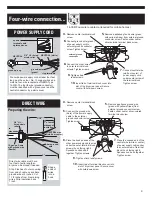
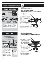
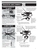
Three-wire power supply cord at least four
feet long must have three, No.-10 copper
wires and match a three-wire receptacle of
NEMA Type 10-30R.

4.

Loosen or remove center terminal

block screw.

6.

Connect the other wires

to outer terminal block
screws. Tighten screws.

7.

Tighten strain relief screws.

8.

Insert tab of terminal block cover into

slot of dryer rear panel. Secure cover
with hold-down screw.

5.

Connect the neutral wire (white

or center) of power supply cord to
the center, silver-colored terminal
screw of the terminal block. Tighten
screw.

POWER SUPPLY CORD

Three-wire connection...

NEUTRAL

NEUTRAL 

(white or center)

3/4" U.L.-listed
strain relief

This blade connected
to this conductor.

ring
terminals

spade
terminals with
upturned ends

Where local codes permit 

connecting cabinet-ground conductor to neutral wire:

10-30R Three-wire  receptacle

Where local codes permit 

connecting cabinet-ground conductor to neutral wire:

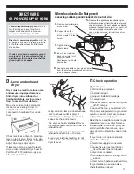
4.

Loosen or remove center terminal
block screw.

7.

Tighten strain relief screws.

8.

Insert tab of terminal block cover
into slot of dryer rear panel.
Secure cover with hold-down
screw.

6.

Place the hooked ends of the
other power supply cable wires
under the outer terminal block
screws (hook facing right).
Squeeze hooked ends together.
Tighten screws.

5.

Place the hooked end of the neutral
wire (white or center) of power
supply cable under the center screw
of the terminal block (hook facing
right). Squeeze hooked end
together. Tighten screw.

DIRECT WIRE

Preparing the wire:

Direct wire cable must have
four feet of extra length so
dryer can be moved if
needed.

Strip 3-1/2 inches of outer
covering from end of cable.
Strip insulation back 1 inch. If
using 3-wire cable with
ground wire, cut bare wire
even with outer covering.

Shape
ends of
wires into
a hook.

10-gauge, 3-wire or,
10-gauge, 3-wire with
ground wire (Romex)

3/4" U.L.-listed
strain relief 

Three-wire with ground wire:
Bare wire cut short. Wire is
not used. Dryer is grounded
through direct wire cable.

to disconnect
box 

NEUTRAL wire
(white or center)

1" of wires
stripped of
insulation

3-1/2"

Summary of Contents for 8535840

Page 1: ...s Failure to complete installation as instructed could void warranty Save Installation Instructions for local inspector s use Have questions about your dryer Call your dealer or local authorized service company When you call you will need the dryer model number and serial number Both numbers are on the model serial rating plate located in the door well behind the dryer door and on front of opening...

Page 2: ...ying performance The location must provide Protection from weather and water Do not store or use dryer where it will be exposed to water and weather Room temperature above 45 F If room temperature is below 45 F automatic cycles may not shut off Level floor Maximum slope under entire dryer should not be more than 1 inch If slope is greater than 1 inch install Extended Dryer Feet Kit Part No 279810 ...

Page 3: ...Whirlpool Parts Accessories 1 800 442 9991 Mon Fri 8am to 9pm CST Sat 9am to 4 30pm CST Visit our internet site at http www whirlpoolappliances com accessories See Page 11 for more information Exhaust hood Do Not use exhaust hoods with magnetic latches 4 4 2 1 2 Preferred Acceptable Mobile home installations require Mobile Home Installation Kit Part Number 346764 Metal exhaust system hardware Floo...

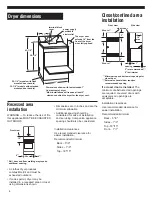
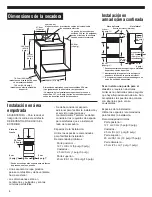
Page 4: ... installation Recommended minimum Back 5 0 Sides 1 0 Top 18 15 Front 1 1 Dryer dimensions 14 power supply cord cable strain relief terminal block cover The dryer door extends 14 from the front of the dryer when fully opened 29 1 4 models with flush mounted door handle 30 1 4 models with extended mounted door handle 43 1 8 11 38 1 4 27 Dimensions shown with feet extended 1 from bottom of dryer Most...

Page 5: ...cold air vent wall ceiling concealed space of a building attic or crawl space or any other vent used for venting Do Not install flexible vent in enclosed walls ceilings or floors Important Observe all governing codes and ordinances Exhaust your dryer to the outside Moisture and lint indoors may cause Lint to gather around the dryer where it can be fuel for a fire Moisture damage to woodwork furnit...

Page 6: ... you have a 4 hood Number of 90 elbows 0 1 2 3 4 Rigid 64 feet 54 feet 44 feet 35 feet 27 feet Flexible fully extended 36 feet 31 feet 27 feet 25 feet 23 feet Maximum length of 4 diameter metal vent When you have a 2 1 2 hood Number of 90 elbows 0 1 2 3 4 Rigid 58 feet 48 feet 38 feet 29 feet 21 feet Flexible fully extended 28 feet 23 feet 19 feet 17 feet 15 feet Typical installations exhaust from...

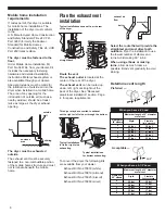
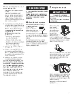
Page 7: ...d Care Guide for a toll free telephone number Installation steps If installing washer and dryer install dryer first SLIDE DRYER ONTO CARDBOARD OR HARDBOARD BEFORE MOVING ACROSS TO PREVENT FLOOR DAMAGE A Install vent system Put on safety glasses and gloves Install exhaust hood Use caulking compound to seal exterior wall opening around exhaust hood Connect exhaust vent to hood Exhaust vent MUST fit ...

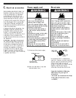
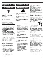
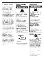
Page 8: ...Disconnect power before making electrical connections Connect neutral wire white or center wire to center terminal silver Ground wire green or bare wire must be connected to green ground connector Connect remaining 2 supply wires to remaining 2 terminals gold Securely tighten all electrical connections Failure to do so can result in death fire or electrical shock WARNING C Electrical connection GR...

Page 9: ...eptacle required for mobile homes 4 Remove center terminal block screw 7 Place the hooked end of the neutral wire white or center of power supply cable under the center screw of terminal block hook facing right Squeeze hook end together Tighten screw 8 Place the hooked ends of the other power supply cable wires under the outer terminal block screws hook facing right Squeeze hooked ends together Ti...

Page 10: ...oosen or remove center terminal block screw 7 Tighten strain relief screws 8 Insert tab of terminal block cover into slot of dryer rear panel Secure cover with hold down screw 6 Place the hooked ends of the other power supply cable wires under the outer terminal block screws hook facing right Squeeze hooked ends together Tighten screws 5 Place the hooked end of the neutral wire white or center of ...

Page 11: ...oor to prevent floor damage Move dryer close to its permanent location Leave enough room to connect exhaust vent Remove cardboard or hardboard from under dryer Check levelness of dryer by placing a level on top of dryer first side to side then front to back If dryer is not level adjust dryer legs up or down If legs are not long enough to level dryer order Extended Dryer Feet Kit Part No 279810 sol...

Page 12: ...old Major Service and Repair SURE CONNECTTM Vent Kit CRUSH RESISTANT Dura SafeTM Kits Make Installation Easy Provides 4 1 2 clearance between dryer and wall Snap Lock fittings Total kit length 8 feet Additional vent can be snapped between sections for longer runs Kit Contains 2 4 vent sections with attached close elbows 1 Wall plate for close clearance installations 2 4 clamps Part 4396028 Section...

Page 13: ...ones podría anular la garantía Conserve las instrucciones de instalación para uso del inspector de instalaciones eléctricas local Tiene preguntas sobre su secadora Llame a su distribuidor o a la compañía de servicios autorizada de su localidad Cuando llame necesitará el número del modelo y el número de serie de la secadora Ambos números están en la placa de modelo serie la cual se encuentra en la ...

Page 14: ...r las posibilidades de lesionarse y le dirán qué podría ocurrir si no se siguen las instrucciones Podría morir o sufrir graves lesiones si no sigue inmediatamente las instrucciones PELIGRO ADVERTENCIA Para el debido funcionamiento de la secadora El lugar debe proporcionar Protección contra la intemperie y el agua no guarde ni utilice la secadora en un lugar donde estaría expuesta al agua y a la in...

Page 15: ...sulte los códigos locales y vea los requisitos eléctricos y de ventilación Paneles A y B antes de comprar pieza alguna Determine si necesitará comprar un juego de cordón de suministro de energía o un cable de suministro de energía Eléctrico Si usa un cordón de suministro de energía El cordón de suministro de energía de la secadora debe ser Aprobado por U L 120 240 voltios mínimo 30 amperios Tipo S...

Page 16: ...facilitar la instalación Recomendados mínimos Parte posterior 12 7 cm 0 cm 5 pulg 0 pulg Costados 2 5 cm 0 cm 1 pulg 0 pulg Parte superior 45 cm 38 1 cm 18 pulg 15 pulg Parte delantera 2 5 cm 2 5 cm 1 pulg 1 pulg Dimensiones de la secadora 35 6 cm 14 pulg La puerta de la secadora se extiende 35 6 cm 14 pulgadas desde el fente de la secadora cuando se abre totalmente 27 9 cm 11 pulg Dimensiones mos...

Page 17: ...nducto flexible en paredes cielos rasos o pisos encerrados Importante Observe todos los códigos y reglamentos aplicables Realice la salida de aire de la secadora a exteriores La humedad y las pelusas a interiores pueden hacer que Las pelusas se acumulen alrededor de la secadora donde se pueden convertir en combustible para un incendio La humedad dañe maderas muebles pintura papel de empapelar alfo...

Page 18: ...ualmente para no retorcerlo 6 4 cm 2 1 2 pulg Aceptable 10 2 cm 4 pulg 10 2 cm 4 pulg Preferido Longitud máxima del conducto metálico de 10 2 cm 4 pulg de diámetro Cuando usted tiene una campana de salida de aire de 10 2 cm 4 pulg Número de codos de 90 0 1 2 3 4 Rigido 19 5 m 64 pies 16 5 m 54 pies 13 4 m 44 pies 10 7 m 35 pies 8 2 m 27 pies Flexible completamente extendido 11 0 m 36 pies 9 4 m 31...

Page 19: ...stá instalando una lavadora y una secadora instale la secadora primero DESLICE LA SECADORA SOBRE UN PEDAZO DE CARTÓN O MADERA DURA ANTES DE MOVERLA PARA NO DAÑAR EL PISO A Instale el sistema de ventilación nueva instalación Póngase gafas protectoras y guantes Instale la campana exterior de salida de aire Use masilla de calafatear para sellar la abertura de la pared exterior alrededor de la campana...

Page 20: ...exiones eléctricas Conecte el alambre neutro el blanco o el del centro con el terminal del centro plateado El alambre de tierra el verde o el desnudo se debe conectar con el conector verde de tierra Conecte los 2 alambres de suministro restantes con los 2 terminales restantes los dorados Apriete firmemente todas las conexiones eléctricas No seguir estas instrucciones puede causar la muerte incendi...

Page 21: ... rodantes 4 Retire el tornillo central del bloque terminal 7 Coloque el extremo en gancho del alambre neutro blanco o central del cable de suministro de energía debajo del tornillo central del bloque terminal con el gancho a la derecha Apriete entre sí los extremos del gancho Apriete el tornillo 8 Coloque los extremos en gancho de los otros alambres del cable de suministro de energía debajo de los...

Page 22: ...s del disp ositivo de protector de cables 8 Inserte la lengüeta de la cubierta del bloque terminal en la ranura del panel posterior de la secadora Asegure la cubierta con el tornillo de retención 6 Coloque los extremos en gancho de los otros alambres del cable de suministro de energía debajo de los tornillos externos del bloque terminal con el gancho a la derecha Apriete entre sí los extremos de l...

Page 23: ...l cordón cable de suministro de energía debajo del tornillo central de color plateado del bloque terminal Apriete el tornillo 9 Conecte un alambre de cobre de conexión a tierra separado del tornillo del conector externo de puesta a tierra a un punto adecuado de conexión a tierra 4 Afloje o retire el tornillo central del bloque terminal ALAMBRE DIRECTO O CORDÓN DE SUMINISTRO DE ENERGÍA Cuando los c...

Page 24: ...7 cm 0 18 pulg 45 7 73 7 cm 18 29 pulg o 73 7 127 cm 29 50 pulg incluyen un accesorio macho de cierre de resorte un collar de banda de tracción extragrande y una abrazadera 21 2 64 mm 2 1 2 pulg Periscopios para instalaciones acodadas e instalaciones estrechas Utilícelo cuando las bocas de salida se solapan o están acodadas El exceso de longitud puede recortarse Periscopios de 45 7 73 7 cm 18 29 p...

Reviews: