background image

6

NOTE: If codes permits, wall venting can be an option for 2-story 
homes.

Calculating Vent System Length

To calculate the length of the system you need, add the 
equivalent feet (meters) for each vent piece used in the system.

Maximum equivalent vent length is 35 ft (10.7 m).

Example Vent System

The following example falls within the maximum vent length of 
35 ft (10.7 m).

Electrical Requirements

Observe all governing codes and ordinances. 

Ensure that the electrical installation is adequate and in 
conformance with National Electrical Code, ANSI/NFPA 70 (latest 
edition), or CSA Standards C22.1-94, Canadian Electrical Code, 
Part 1 and C22.2 No. 0-M91 (latest edition) and all local codes 
and ordinances.

If codes permit and a separate ground wire is used, it is 
recommended that a qualified electrician determine that the 
ground path is adequate.

A copy of the above code standards can be obtained from:

National Fire Protection Association

1 Batterymarch Park

Quincy, MA 02169-7471

CSA International

8501 East Pleasant Valley Road

Cleveland, OH 44131-5575

A 120 volt, 60 Hz., AC only, 15-amp, fused electrical circuit is 
required.

If the house has aluminum wiring, follow the procedure 
below:

1. Connect a section of solid copper wire to the pigtail 

leads.

2. Connect the aluminum wiring to the added section of 

copper wire using special connectors and/or tools 
designed and UL listed for joining copper to aluminum.

Follow the electrical connector manufacturer's recommended 
procedure. Aluminum/copper connection must conform with 
local codes and industry accepted wiring practices.

Wire sizes and connections must conform with the rating of 
the appliance as specified on the model/serial rating plate. 
The model/serial plate is located behind the filter on the rear 
wall of the range hood.

Wire sizes must conform to the requirements of the National 
Electrical Code, ANSI/NFPA 70 (latest edition), or CSA 
Standards C22. 1-94, Canadian Electrical Code, Part 1 and 
C22.2 No. 0-M91 (latest edition) and all local codes and 
ordinances.

Non-vented (recirculating)

Roof Venting

A. Deflector
B. 6" (15.2 cm) round vent

A. Roof cap
B. 6" (15.2 cm) round vent

Vent piece

6" (15.2 cm) round

45° elbow

2.5 ft
(0.8 m) 

90° elbow

5.0 ft
(1.5 m)

1 - 90° elbow

= 5.0 ft (1.5 m)

1 - wall cap

= 0.0 ft (0.0 m)

8 ft (2.4 m) straight

= 8.0 ft (2.4 m)

System length

= 13 ft (3.9 m)

B

A

B

A

90  elbow

6 ft (1.8 m)

2 ft

(0.6 m)

Wall cap

Summary of Contents for 36" (91.4 CM) GAS BUILT-IN COOKTOP

Page 1: ...ebsite at www whirlpool ca HOTTE DE CUISINIÈRE CONFIGURÉE EN ÎLOT 36 91 4 CM Instructionsd installationetGuided utilisationetd entretien Au Canada pour assistance installation ou service composer le 1 800 807 6777 ou visiter notre site Web à www whirlpool ca Table of Contents Table des matières 2 IMPORTANT READ AND SAVE THESE INSTRUCTIONS FOR RESIDENTIAL USE ONLY IMPORTANT LIRE ET CONSERVER CES IN...

Page 2: ...NTRETIEN DE LA HOTTE 28 Nettoyage 28 SCHÉMA DE CÂBLAGE 29 ASSISTANCE OU SERVICE 30 Au Canada 30 Accessoires 30 GARANTIE 31 RANGE HOOD SAFETY You can be killed or seriously injured if you don t immediately You can be killed or seriously injured if you don t follow All safety messages will tell you what the potential hazard is tell you how to reduce the chance of injury and tell you what can happen ...

Page 3: ...zardous or explosive materials and vapors CAUTION To reduce risk of fire and to properly exhaust air be sure to duct air outside do not vent exhaust air into spaces within walls or ceilings attics or into crawl spaces or garages WARNING TO REDUCE THE RISK OF FIRE USE ONLY METAL DUCTWORK WARNING TO REDUCE THE RISK OF A RANGE TOP GREASE FIRE Never leave surface units unattended at high settings Boil...

Page 4: ...rial rating plate The model serial rating plate is located behind the left filter on the rear wall of the vent hood Canopy hood location should be away from strong draft areas such as windows doors and strong heating vents Cabinet opening dimensions that are shown must be used Given dimensions provide minimum clearance Grounded electrical outlet is required See Electrical Requirements section Beca...

Page 5: ...ermal break should be installed to minimize conduction of outside temperatures as part of the vent system The damper should be on the cold air side of the thermal break The break should be as close as possible to where the vent system enters the heated portion of the house Makeup Air Local building codes may require the use of makeup air systems when using ventilation systems greater than specifie...

Page 6: ...15 amp fused electrical circuit is required If the house has aluminum wiring follow the procedure below 1 Connect a section of solid copper wire to the pigtail leads 2 Connect the aluminum wiring to the added section of copper wire using special connectors and or tools designed and UL listed for joining copper to aluminum Follow the electrical connector manufacturer s recommended procedure Aluminu...

Page 7: ... cooking surface 2 Tape template in place on the ceiling at the marked centerline The line for the front of the range hood should be parallel to the front of the cooktop 3 Use a pencil to mark the mounting screws wire access and duct hole locations on the ceiling NOTE Mounting hole locations should be into a ceiling support structure capable of holding 80 lbs 36 6 kg Remove the template 4 Drill 4 ...

Page 8: ...irements section to help determine the desired dimension for vertical height B Secure with 16 4 2 x 8 mm T20 screws InstallRangeHood Non Vented recirculating Installation 1 Attach the air deflector to the upper horizontal support using 4 mounting screws 2 Measure the length of 6 15 2 cm duct needed to connect the transition to the deflector NOTE Vent should fit up inside the deflector 1 2 5 cm min...

Page 9: ...bulbs are secure in their sockets 11 Reconnect power Optional Power Cord Kit Installations For optional power cord kit installations follow the instructions supplied with the power cord kit See the Assistance or Service section for information on ordering NOTE Use only with range hood cord connection kits that have been investigated and found acceptable for use with this model range hood A Mountin...

Page 10: ...ower duct cover 5 Install the lower duct cover front to the range hood canopy Spread the lower duct cover opening slightly and position it over the upper duct cover Set the lower duct cover in place Position so the flanges of the lower duct cover set into the flanges of the upper duct covers 6 Install the lower duct cover rear to the range hood canopy Spread the lower duct cover opening slightly a...

Page 11: ...n vented recirculating installations only install charcoal filters onto the metal filters See the Range Hood Care section 2 Install metal filters See the Range Hood Care section 3 Check the operation of the range hood blower and light See the Range Hood Use section If range hood does not operate check to see whether a circuit breaker has tripped or a household fuse has blown NOTE To get the most e...

Page 12: ...ating the Ambient Lighting The switch controls the ambient lighting 1 Press to the left to turn AUTO On 2 Press to the right to turn AMBIENT LIGHTING On 3 Press to the center to turn AMBIENT LIGHTING or AUTO Off NOTE When the Ambient Lighting is placed in the AUTO setting a sensor will automatically sense if it is dark in the area around the range hood The Ambient Lighting will turn on and stay on...

Page 13: ...as needed in dishwasher or hot detergent solution 4 Reinstall the filter by making sure the spring release handles are toward the front Insert aluminum filter into upper track 5 Push in spring release handle 6 Push up on metal filter and release handle to latch into place Non Vented recirculating Installation Filters The charcoal filter is not washable It should last up to 6 months with normal use...

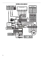
Page 14: ...RD BU Strip LED Strip LED RD BK RD BK BK BU BU RD RD BK BU WH BK WH BK LED LED SE136A M 1 2 3 4 5 6 7 8 9 YL GN BR YL GN BR YL YL WH RD BK BU BU GR BK RD WH BK YL BU Light Sensor Turns on at 10 LUX Turns off at 50 LUX Input Output P1 P2 P4 P3 Push Button Switch Operation Function Position Off Lamps Low Speed Med Speed High Speed No Connection Brown Black L 3 Brown Red L 2 Brown White L 1 Brown Yel...

Page 15: ...istance you can write to Whirlpool Corporation with any questions or concerns at Whirlpool Brand Home Appliances Customer eXperience Center 553 Benson Road Benton Harbor MI 49022 2692 Please include a daytime phone number in your correspondence InCanada Call the Whirlpool Canada LP Customer eXperience Centre toll free 1 800 807 6777 or visit our website at www whirlpool ca Our consultants provide ...

Page 16: ...ble parts i e light bulbs batteries air or water filters preservation solutions etc 5 Conversion of products from natural gas or L P gas 6 Damage from accident misuse abuse fire floods acts of God or use with products not approved by Whirlpool 7 Repairs to parts or systems to correct product damage or defects caused by unauthorized service alteration or modification of the appliance 8 Cosmetic dam...

Page 17: ...areil ménager Assurez vous de toujours lire tous les messages de sécurité et de vous y conformer AVERTISSEMENT DANGER Voici le symbole d alerte de sécurité Ce symbole d alerte de sécurité vous signale les dangers potentiels de décès et de blessures graves à vous et à d autres Tous les messages de sécurité suivront le symbole d alerte de sécurité et le mot DANGER ou AVERTISSEMENT Ces mots signifien...

Page 18: ...die et évacuer adéquatement les gaz veiller à acheminer l air aspiré par un conduit jusqu à l extérieur ne pas décharger l air aspiré dans un espace vide du bâtiment comme une cavité murale un plafond un grenier un vide sanitaire ou un garage AVERTISSEMENT POUR RÉDUIRE LE RISQUE D INCENDIE UTILISER UNIQUEMENT DES CONDUITS MÉTALLIQUES AVERTISSEMENT POUR MINIMISER LE RISQUE D UN FEU DE GRAISSE SUR L...

Page 19: ...l La plaque signalétique de l appareil est située derrière le filtre de gauche sur la paroi arrière de la hotte On doit toujours installer la hotte à distance des sources de courant d air fort fenêtres portes et bouches de chauffage à fort débit Respecter les dimensions indiquées pour les ouvertures à découper dans les placards Ces dimensions tiennent compte des valeurs minimales des dégagements d...

Page 20: ...ue pour minimiser le transfert de chaleur par conduction vers l extérieur Le clapet anti reflux doit être placé du côté air froid par rapport à l élément d isolation thermique L élément d isolation thermique doit être aussi proche que possible de l endroit où le système d évacuation s introduit dans la partie chauffée de la maison Air d appoint Le code du bâtiment local peut exiger l emploi d un s...

Page 21: ...ble Si le domicile possède un câblage en aluminium suivre la procédure ci dessous 1 Raccorder une section de câble en cuivre massif aux conducteurs en queue de cochon 2 Connecter le câblage en aluminium à la section ajoutée de câblage en cuivre en utilisant des connecteurs et ou des outils spécialement conçus et homologués UL pour fixer le cuivre à l aluminium Suivre la procédure recommandée par l...

Page 22: ...rer que la hotte est bien centrée par dessus la surface de cuisson 2 Fixer le gabarit au plafond avec du ruban adhésif au niveau de l axe central Le bord avant de la hotte de cuisinière doit être parallèle au bord avant du plan de travail 3 À l aide d un crayon marquer au plafond l emplacement des vis de montage du point d accès au câblage et du trou de passage du conduit REMARQUE Le montage de l ...

Page 23: ...s et fixer la hotte à l aide des 16 vis de 4 2 x 8 mm 3 Fixer le support horizontal B à l aide des 8 vis de 4 2 x 8 mm 4 Fixer un deuxième ensemble de supports verticaux A et régler la hauteur verticale B Voir Dégagements pour l installation dans la section Exigences d emplacement pour déterminer la dimension souhaitée pour la hauteur verticale B Fixer avec 16 vis T20 de 4 2 x 8 mm Installationdel...

Page 24: ...e arrachable du boîtier de connexion et installer un serre câble de homologation UL ou CSA 4 Acheminer le cordon d alimentation du domicile à travers le serre câble dans le boîtier de connexion 5 Connecter ensemble les conducteurs noirs C à l aide de connecteurs de fils homologation UL 6 Connecter ensemble les conducteurs blancs E à l aide de connecteurs de fils homologation UL A Vis de montage A ...

Page 25: ...ort Le trou le plus gros sur les rebords de la partie supérieure du cache conduit doit se trouver à l extérieur du trou le plus petit sur le rebord en contact de l autre partie supérieure du cache conduit 2 Fixer ensemble la partie supérieure des cache conduits avec 2 vis de 3 5 x 6 5 mm sur le haut et 2 vis de 2 9 x 3 mm sur le bas Installer 1 vis de chaque côté du haut et du bas des cache condui...

Page 26: ...de la partie inférieure du cache conduit se placent dans les rebords de la partie supérieure du cache conduit S assurer que les parties inférieures avant et arrière des cache conduits communiquent correctement REMARQUE Lors de l assemblage de la partie inférieure arrière du cache conduit à la partie inférieure avant le rebord des deux côtés doit être placé par dessus la cheville en plastique afin ...

Page 27: ...ois pour Off arrêt Utilisation du ventilateur Les boutons Blower Speed vitesse du ventilateur activent le ventilateur et contrôlent la vitesse du ventilateur et le niveau sonore pour un fonctionnement silencieux On peut modifier la vitesse à tout moment pendant le fonctionnement du ventilateur en appuyant sur le bouton de vitesse du ventilateur souhaité Le bouton Blower Off arrêt ventilateur étein...

Page 28: ...nstaller le filtre en s assurant que les poignées à ressort sont orientées vers l avant Insérer le filtre à graisse métallique dans la rainure supérieure 5 Tirer sur la poignée à ressort 6 Pousser le filtre métallique vers le haut et relâcher la poignée pour l emboîter Filtres d installation sans décharge à l extérieur recyclage Le filtre à charbon n est pas lavable Celui ci devrait durer pendant ...

Page 29: ... Rampe de DEL R N R N N BU BU R R N BU BL N BL N DEL DEL SE136A M 1 2 3 4 5 6 7 8 9 JA VE MAR JA VE MAR JA JA BL R N BU BU GRIS N R BL N JA BU Capteur de lumière S allume à 10 lux S éteint à 50 lux Entrée Sortie P1 P2 P4 P3 Fonctionnement du commutateur du bouton poussoir Fonction Position Arrêt Lampes Vitesse basse Vitesse moyenne Vitesse élevée Pas de connexion Marron Noir L 3 Marron Rouge L 2 M...

Page 30: ... remplir la garantie des produits et fournir un service après garantie partout au Canada Caractéristiques et spécifications sur toute notre gamme d appareils électroménagers Références aux marchands locaux Consignes d utilisation et d entretien Vente d accessoires et de pièces de rechange Pour plus d assistance Si vous avez besoin de plus d assistance vous pouvez soumettre par écrit toute question...

Page 31: ...à eau solutions de conservation etc 5 Conversion de votre produit du gaz naturel ou du gaz de pétrole liquéfié 6 Dommages causés par accident mésusage abus incendie inondations catastrophe naturelle ou l utilisation de produits non approuvés par Whirlpool 7 Réparations aux pièces ou systèmes dans le but de rectifier un dommage ou des défauts résultant d une réparation altération ou modification no...

Page 32: ...W10674117A 2014 Whirlpool Used under license in Canada All rights reserved Utilisé sous licence au Canada Tous droits réservés 6 14 Printed in Mexico Imprimé au Mexique ...

Reviews: