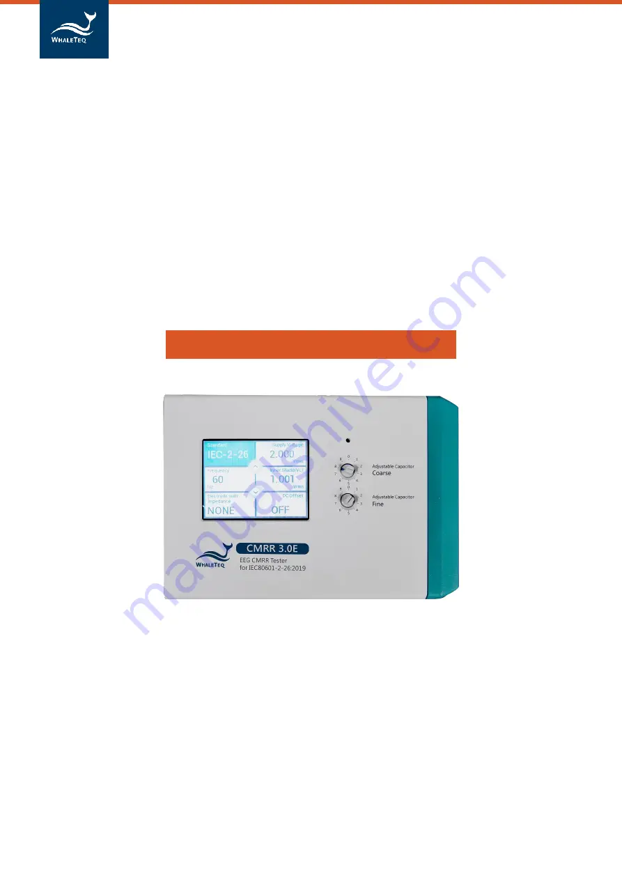
CMRR 3.0E | User Manual
WHALETEQ
Common Mode Rejection Ratio Tester
For IEC80601-2-26:2019
CMRR 3.0E User Manual
(Revision 2020-09-03)
PC Software Version V1.0.6.9
Page 1: ...CMRR 3 0E User Manual WHALETEQ Common Mode Rejection Ratio Tester For IEC80601 2 26 2019 CMRR 3 0E User Manual Revision 2020 09 03 PC Software Version V1 0 6 9 ...
Page 2: ...and the programs as is without warranty of any kind either expressed or implied including but not limited to the implied warranties of merchantability or fitness for a particular purpose This document could contain technical inaccuracies or typographical errors Changes are periodically made to the information herein these changes will be incorporated in future revisions of this document WhaleTeq C...
Page 3: ...ed Hole 11 5 2 2 USB Connector 11 5 2 3 DC 12V Terminal 11 5 2 4 Power Switch 12 5 2 5 Vc Terminal 12 5 2 6 Vs Terminal 12 5 2 7 Monitor Terminal 12 5 2 8 Grounding Terminal 12 5 3 Right Panel 12 5 3 1 CM Point Terminal 13 5 3 2 RA LA LL RL V1 V6 Electrode Terminals 13 6 Operation 13 6 1 Stand alone Operation 13 6 1 1 Touch Screen for Setting Different Parameters 13 6 1 2 Test Exemplification 16 6...
Page 4: ...CMRR 3 0E User Manual 4 9 Ordering Information 22 9 1 Package Contents 22 9 2 Optional Software and Accessories 22 10 Contact Information 22 ...
Page 5: ...toring applied voltages in the calibration process For Monitor output terminal it s designed to confirm voltage value Vc Due to the high impedance brought by 100 pF at 50 60 100 120hz this causes typical multimeters being not able to measure precisely Besides it requires non load output voltage at 10 Vrms in certain IEC standards Therefore WhaleTeq CMRR 3 0E uses 11 1 110MΩ 10MΩ voltage divider an...
Page 6: ...d control circuit signal generator 7 Voltage monitor Vs Vc 8 User control unit Switch USB 9 MCU 10 LCD display module 6 and 6A are the isolated circuits for isolating noises existed in power source and signal 3 Set Up a Noise Free Test Environment 3 1 Reduce environmental noise and connect outer shielding to the ground plane It s a must to reduce noise when testing EEG Please refer to the below de...
Page 7: ...al bench to connect to the common ground plane Figure 3 1 Set up CMRR 3 0E Test Environment 3 2 Shielding Covers for the Electrode Cables 1 Please fasten the bottom shielding cover to the right side panel of CMRR 3 0E for reducing main frequency interference see Figure 3 2 Figure 3 2 CMRR 3 0E with bottom shielding cover 2 As the bottom shielding cover is connected to Vc Vc would be unstable due t...
Page 8: ...ce the common mode voltage is usually not more than 10 times the differential voltage so a CMRR of 60dB would only result in a 0 1 error The most common source of common mode noise is mains voltages i e 50 60Hz Thus CMRR in meters is usually specified at these frequencies But it is important to note that CMRR varies with frequency Common mode rejection also varies with the impedance of the source ...
Page 9: ...th the imbalance readings typically range between 3 7mm 0 3 0 7mVpp This suggests that the value of imbalance impedance is critical for the tests Although the diagram in the standard shows all switches open for the purpose of the test all switches should be closed except the lead being tested and some tests are in the opposite settings instead CMRR 3 0E uses MCU to control the relay switch which m...
Page 10: ...rrow button or the down arrow button to switch between different options For example you can click the arrow bottom to quickly switch Off 20 2 828 0 5 and 2 0 Vrms for Supply Voltage under Manual standard Otherwise user can double click the function to have all the options shown in a separated page 5 1 2 Coarse Knob Located at the right side of the LCD display it is used to tune adjustable capacit...
Page 11: ...elected to test a higher CMRR value 5 2 Front Panel The front panel of CMRR 3 0E is shown in figure 5 2 Please see instruction to each terminal as below Figure 5 2 the front panel of CMRR 3 0E Connectors on the front panel are mainly used for power supply USB connection and calibration 5 2 1 Tapped Hole The front and back panels each has two tapped holes for fastening the shielding cover or the sh...
Page 12: ...0E built in sine wave signal generator This is intended for use in equipment calibration 5 2 7 Monitor Terminal The output terminal of inner common mode point after it passes through 11 1 voltage divider It measures the voltage of Vc decayed by a factor of 11 directly This is intended for use in equipment calibration 5 2 8 Grounding Terminal Outer shield grounding that connects the metal sheet in ...
Page 13: ...the switch at the right side to be turned to On All of the operations of CMRR 3 0E can be done with the touch screen and knobs on the upper panel All the parameters can be displayed on the LCD touch screen 6 1 1 Touch Screen for Setting Different Parameters The touch screen can be used for selecting different functions such as Standard Supply Voltage Frequency Inner Shield Vc Electrode with Impeda...
Page 14: ... test a CMRR value that exceeds the requirement of standards Although this voltage exceeds all of the standard requirements it extends the range of CMRR value Figure 6 2 Options in Supply Voltage and Frequency 6 1 1 3 Inner Shield Vc Once Supply Voltage Vs is selected the Coarse Fine knobs can be tuned to Inner shield Vc Vs 2 This action automatically measures and monitors the voltage that passes ...
Page 15: ...th Impedance RA LA LL V1 V6 only RA LA LL V1 V6 is added 10KΩ 47nF and the other electrodes are not imbalanced test Electrode with Impedance All all of the electrodes are added 10KΩ 47nF parallel circuit balanced test Electrode without Impedance RA LA LL V1 V6 all of the electrodes are added 10KΩ 47nF except RA LA LL V1 V6 imbalanced test Figure 6 4 options in Electrode with Impedance 6 1 1 5 DC O...
Page 16: ...roceed balance and imbalance tests with DC offset options This is to ensure the absolute balance of CMRR 3 0E output signals and increase the precision of CMRR test The following test procedures are all followed the requirements stated in IEC80601 2 26 and can be taken as test examples of CMRR 3 0E Due to the different naming rules between EEG and ECG standards hereby we use Ch1 Ch2 etc to prevent...
Page 17: ...ful add on software provided by WhaleTeq which enables PC to control CMRR 3 0E parameter setting and simplify standards into selectable options including test sequences required by each standard 6 2 1 CMRR 3 0E PC Software CMRR 3 0E PC software can control all the test parameters except adjusting Vc value via coarse knob and fine knob Once CMRR 3 0E is connected to PC through USB interface CMRR 3 ...
Page 18: ... complication of switching different test parameters Once select IEC 2 26 standard follow the software guide to go through the setting of test parameters Also the test can be conducted manually or automatically Here we take IEC 2 26 as an example to explain the test sequences 6 2 2 1 Step 1 Preparation First after clicking IEC 2 26 the test step automatically starts at Step 1 Preparation It also e...
Page 19: ...r understanding of the test sequences Figure 6 8 Software interface and test sequence description of CMRR 3 0E Assistant 6 2 2 2 Step 2 Frequency Setting Set the line frequency to either 50Hz or 60Hz or both When both frequencies are selected the setting of 50Hz will be performed first and the same setting would be performed automatically with frequency replaced with 60Hz 6 2 2 3 Step 3 Connection...
Page 20: ...nd shown at the upper right corner with total test time shown below it After recording the test result please click Next The setting will be automatically switched to Electrode with Impedance RA and the time at the upper right corner will be returned to zero and counted in second again Figure 6 9 Software interface and run test windows of CMRR 3 0E Assistant The display of Test Sequence is shown a...
Page 21: ... be performed without any concern from noise arising from internal or external switching power supplies 7 2 Battery power consumption for DC offset function CMRR 3 0E uses a built in battery supplying the power required by DC offset option Before turning off the power user must check and confirm DC offset is switched to OFF If not it would keep consuming battery power in the power off status 7 3 V...
Page 22: ...mV 1 Up to 40hrs with intermittent use 100 pF capacitor Use 11 1 110MΩ 10MΩ voltage divider to measure indirectly 100pF 5 Environment Intended for normal laboratory environment The selection of critical components is known to be stable in the range shown The 110MΩ divider may be affected by high humidity in excess of 85 15 30 C 10 75 RH 9 Ordering Information 9 1 Package Contents CMRR 3 0E x 1 CMR...