Whalen BBXL54NV Assembly Manual Download Page 21

Model # BBXL54NV 

Please call for replacement parts or assistance: 

1-866-942-5362


Whalen Furniture Manufacturing   


           Page 21                                 Factory No. 16434 


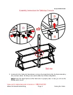
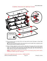
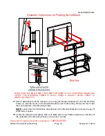
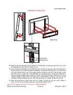
Assembly Instructions for Universal Wall Mount 

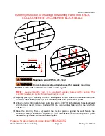
Installing the Mounting Frame onto a WOODEN STUD WALL 


NOTE

: If you are mounting your TV onto brick, solid concrete or concrete block walls, skip this 

section. This assembly requires an electric drill, level and stud finder (not included). 


32. Using a stud finder, locate the edges of the wood studs. Find the center line of each stud and 

draw a vertical reference line on the wall over each one. Place the Mounting Frame (J) level 
against the wall where you intend to mount the TV. Using the Mounting Frame (J) as a 
template, mark 4 drill points (2 on top, 2 on bottom) with a pencil on the vertical reference lines 
you just drew. 

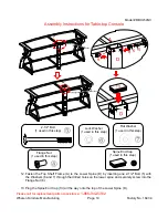
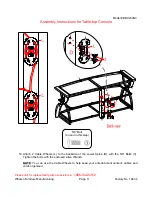
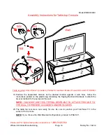
33. With an electric drill (not included), drill 3/16 inch diameter holes to at least 2½ inch deep on 

the 4 drill points. While holding the Bracket Plate in place, loosely screw in the Lag Bolts (11). 

34. Secure the Mounting Frame (J) to wall with Lag Bolts (11) and the Washers (12) at the drill 

points. Tighten the bolts firmly, but be careful not to over-tighten. 


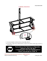
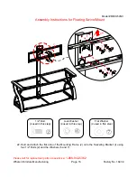
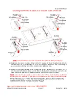
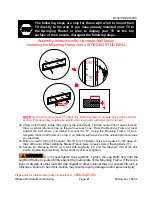
The following steps are only for those who wish to mount their 
TV directly to the wall. If you have already mounted your TV to 
the Swinging Floater or plan to display your TV on the top 
surface of the Console, disregard the following steps. 

Do not over-tighten the Lag Bolts. Tighten the Lag Bolts only until the 

Lag Bolt Washer is pulled firmly against the metal plate of the Mounting Frame. If there is a 
layer of drywall or other material, this drywall or other material may not exceed 5/8 inch in 
thickness. Failure to heed this caution may result property damage and/or personal injury.


2.50" (63 mm)

0

.20"

 (5 m

m

)

Summary of Contents for BBXL54NV

Page 1: ...configurations at a later date if desired ADULT ASSEMBLY REQUIRED If you have any questions regarding assembly or if parts are missing DO NOT return this item to the store where it was purchased Plea...

Page 2: ...GENERAL INFORMATION TIPS and TRICKS This product is sold with one set of Tipping Restraint Hardware Kit You must install the Tipping Restraint Hardware between the wall and the TV console to prevent...

Page 3: ...dware are present before beginning assembly A Top Shelf Frame 1 B Middle Shelf Frame 1 C Bottom Shelf Frame 1 D Spine Assembly 1 E Left Leg 1 F Right Leg 1 G Top Glass 1 H Glass Shelf 2 I Swiveling Br...

Page 4: ...chor 4 11 2 1 2 Lag Bolt 4 12 Large Flat Washer 4 1 extra 13 Spine End Cap 1 14 Acrylic Stopper 1 M4 Allen Wrench 2 Touch up Pen 1 Tipping Restraint Hardware Kit 1 Inside Plastic Bag TV Mounting Kit M...

Page 5: ...r 1 Unpack the unit and confirm that you have all the hardware and required parts 2 Locate the Spine Assembly D and set the back face down on a scratch free surface as shown 3 Align and attach the She...

Page 6: ...es Secure the Left Leg E to the Bottom Shelf Frame C by using one 5 8 Bolt 3 with the Washers 6 and 7 through the metal bracket and screw into place DO NOT tighten the bolts in this step 6 Securely fa...

Page 7: ...434 Assembly Instructions 8 Secure the Top Shelf Frame A to the inner metal legs E and F using two 5 8 Bolts 3 with the Washers 6 and 7 through the top metal plate of each leg and securely screw into...

Page 8: ...sembly Instructions 9 Go back and tighten all bolts with the enclosed Allen Wrench 10 If necessary adjust the pre attached Floor Levelers at the bottom of both Legs E and F to level the unit If you ch...

Page 9: ...o 16434 Assembly Instructions for Table top Console 11 Unscrew the four bolts and the washers to remove the Upper Spine from the Spine Assembly D as shown above So that you can use the table top conso...

Page 10: ...to the Lower Spine D by inserting one 2 1 2 Bolt 5 with the Washers 6 and 7 through the drilled holes on the lower spine and securely screw into the Flange Nut 8 13 Plug the Spine End Cap 13 all the...

Page 11: ...ory No 16434 Assembly Instructions for Table top Console 14 Attach 2 Cable Wheels L to the backside of the Lower Spine D with the 5 8 Bolts 3 Tighten the bolts with the enclosed Allen Wrench NOTE You...

Page 12: ...of the cup with the Allen Wrench while twisting it clockwise into the hole 16 Place the Glass Shelves G and H with the black side of the glass down onto the Suction Cups 1 on shelf frames as shown abo...

Page 13: ...e Acrylic TV Stopper to prevent the TV from tipping when placing your flat panel television directly on the console 17 Remove the tape of the Acrylic Stopper 14 and place it in the cut out of the Acry...

Page 14: ...d console at the desired location against a wall Now follow the instructions printed on the plastic bag containing the Tipping Restraint Hardware to attach the tip over restraint to the spine and the...

Page 15: ...four 5 8 Bolts 3 and four Washers 6 and 7 Turn the Swiveling Bracket against the Upper Spine D when tightening the bolts with the enclosed M4 Allen Wrench Make sure the pivoting bolt head faces up NO...

Page 16: ...ing Page 16 Factory No 16434 Assembly Instructions for Floating Swivel Mount 22 Hold and attach the flat side of the Mounting Frame J onto the Swiveling Bracket I using four 1 2 Bolts 2 and the Washer...

Page 17: ...t on the back of the TV If you encounter any resistance stop immediately If you are unable to find the correct bolt consult a local hardware store 24 Follow the appropriate diagram above to attach the...

Page 18: ...ny resistance stop immediately If you are unable to find the correct bolt consult a local hardware store 26 Follow the appropriate diagram above to attach the Monitor Brackets K to the back of the TV...

Page 19: ...INSTALLATION OF TV 27 Ask for assistance to lift the television up to hang the Monitor Brackets K onto the Mounting Frame J Set the hooks on the Monitor Brackets over the Mounting Frame and then lowe...

Page 20: ...e Wheels L to the Spine and install the Glass Shelves G and H into place 30 Carefully move the console and position it at the desired location against a wall Now follow the instructions printed on the...

Page 21: ...ines you just drew 33 With an electric drill not included drill 3 16 inch diameter holes to at least 2 inch deep on the 4 drill points While holding the Bracket Plate in place loosely screw in the Lag...

Page 22: ...Using the Mounting Frame J as a template mark 4 drill points with a pencil 36 With an electric drill not included on its low setting drill 7 16 inch diameter holes to at least 2 inch deep Insert Conc...

Page 23: ...the Mounting Frame J Set the hooks of the Monitor Brackets over the Mounting Frame and then lower them onto the bars of the Mounting Frame Loosen the Lock Bolts that are pre attached on the Monitor B...

Page 24: ...advice about furniture care It is best to keep your furniture in a climate controlled environment Extreme temperature and humidity changes can cause fading warping shrinking and splitting of wood It i...

Page 25: ...BBXL54NV 8 MF Mounting Frame BBXL54NV 26 FW Flat Washer BBXL54NV 9 MB Monitor Bracket BBXL54NV 27 FN Flange Nut BBXL54NV 10 LB Lock Bolt BBXL54NV 28 2 1 2LB 2 1 2 Lag Bolt BBXL54NV 11 CW Cable Wheel...

Reviews: