BUILD INSTRUCTIONS
Start by building PCB-A. Start with
diodes, resistors, ferrite beads, then
caps, then DIP sockets, connectors, and
finally THT transistors.
© 2020 Weston Precision Audio
6
AD110 PCB-A Rev BB Build Table
Reference
Quantity Value
Footprint / Note
C101 C107
2 4.7n Film 5%
Film “box” type. 5% Tolerance or hand select.
C102 C103
2 3.3n Film
Film “box” type
C104 C130 C122 C123
4 470p
Multilayer ceramic radial
C108 C127 C134 C106 C111
5 1n Film
Film “box” type
C110
1 4.7u
Raidal electrolytic
C113 C138
2 100u
Raidal electrolytic
C114 C119
2 10n Film 5%
Film “box” type. 5% Tolerance or hand select.
C115 C116
2 6.8n Film
Film “box” type
C117 C126
2 47n Film
Film “box” type
C118
1 33p
Multilayer ceramic radial
C120 C128 C132 C109
4 2.2n Film
Film “box” type
C125 C131 C105
3 10n
Multilayer ceramic radial
C129 C121 C124
3 1u
Raidal electrolytic
C133
1 470p
Multilayer ceramic radial
C135 C112
2 0.47u
Multilayer ceramic radial
C136 C137 C143
3 33u
Raidal electrolytic
C139 C140 C141 C142 C144 C145
6 100n
Multilayer ceramic radial
D102 D103 D106 D107 D101 D104 D105
7 1SS133M
General purpose diode
D108 D109
2 1N4001
Rectifier diode
D110
1 TZX9V1D
Zener diode
J101
1 Eurorack Power
Boxed/Keyed 10-pin connector.
Install on back side of board.
JP111
1 A/B Interconnect 1 2.54mm Pin Socket, 6 position.
Install front side of board.
JP112
1 A/B Interconnect 2 2.54mm Pin Socket, 6 position.
Install front side of board.
JP115
1 A/B Interconnect 3 2.54mm Pin Socket, 12 position.
Install front side of board.
L101 L102
2 Ferrite
Ferrite bead axial
Q107 Q110 Q102
3 BC559B
Transistor, BJT, TO-92 Inline package
Q109 Q108 Q106 Q111 Q101 Q103 Q104 Q105
8 BC549B
Transistor, BJT, TO-92 Inline package
R101 R127 R158
3 82k
1% Metal film resistor axial
R102 R113 R126 R136
4 100k 0.1%
0.1% Metal film resistor axial
R103
1 442k
1% Metal film resistor axial
R106 R155 R171 R123 R119
5 10k
1% Metal film resistor axial
R107
1 86.6k 0.1%
0.1% Metal film resistor axial
R110 R133
2 560R
1% Metal film resistor axial
R114 R128 R156 R168
4 22k
1% Metal film resistor axial
R116
1 2.2M
1% Metal film resistor axial
R117
1 127k 0.1%
0.1% Metal film resistor axial
R122
1 20k
1% Metal film resistor axial
R124 R161
2 220k
1% Metal film resistor axial
R125 R105 R108 R121 R132 R138 R151 R163 R147 R150 R165 R169
R109 R112 R115 R129
16 100k
1% Metal film resistor axial
R130
1 107k 0.1%
0.1% Metal film resistor axial
R131 R148
2 2M
1% Metal film resistor axial
R134
1 47k
1% Metal film resistor axial
R135
1 39k
1% Metal film resistor axial
R139 R149 R162 R159 R167 R111 R142 R143
8 33k
1% Metal film resistor axial
R140
1 158k 0.1%
0.1% Metal film resistor axial
R141
1 374R
1% Metal film resistor axial
R144
1 68k
1% Metal film resistor axial
R145
1 27k
1% Metal film resistor axial
R146 R160 R104
3 200k
1% Metal film resistor axial
R152 R164 R137
3 1k
1% Metal film resistor axial
R153 R170 R120
3 5.6k
1% Metal film resistor axial
R154 R166 R118
3 220R
1% Metal film resistor axial
R157
1 470k
1% Metal film resistor axial
R172
1 330R
1% Metal film resistor axial
U102
1 CD4070
DIP 14 Socket
U104
1 TL072
DIP 8 Socket
U105 U101
2 CD4069
DIP 14 Socket
U106
1 CD4006
DIP 14 Socket
U107
1 TL074
DIP 14 Socket
U108 U103
2 CD4098
DIP 16 Socket
1
Summary of Contents for AD110
Page 12: ...REF Finished Unit 2020 Weston Precision Audio 12...
Page 13: ...REF PCB Pics Finished 2020 Weston Precision Audio 13...
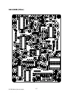
Page 17: ...SILKSCREEN PCB A 2020 Weston Precision Audio 17...
Page 18: ...SILKSCREEN PCB B 2020 Weston Precision Audio 18...
Page 19: ...SILKSCREEN PCB C 2020 Weston Precision Audio 19...


