THEORY OF OPERATION
The resonant “drum” portion of both the
snare drum and kick drum are the same
type of circuit, which is known as a
“damped oscillator” circuit. This circuit
oscillates at a frequency which is
determined by the resistors and
capacitors in the T-Networks when it is
hit with an impulse (i.e the negative
going pulse on the Qbar outputs of
Monostable U202, and decays naturally
until it is hit again with an impulse. The
snare drum has an additional VCA
profile which occurs in unison with the
drum sound portion and gates a filtered
noise source to produce the sound of the
snare wires.
Speaking of VCAs, all of the drum
circuits which have a VCA use an
extremely simply design which works
basically in reverse from a standard
VCA. The “signal” is essentially an
Attack-Decay envelope formed by an RC
network and this envelope is gated
through a diode and transistor by a
control signal, be it noise, or the cymbal
frequencies. Not a hi-fi VCA by any
means, but it is SIMPLE and it is
effective!
The cymbal sounds (Open and closed hi
hat and cymbal) all are formed by
gating a mix of fundamental frequencies
through the VCAs mentioned above. The
4 cymbal frequencies are commonly
found in various analog drum machines
of the time. They are formed via simple
CMOS inverter oscillators in U101 and
U105 and are approximately 305Hz,
44Hz, 794Hz, and 1136Hz. These 4
signals are mixed together and filtered
with another T network in U104A and
U104B to form the final cymbal tones
CYMOSC1 and CYMOSC2.
The noise source, which is utilized to
form the basis of the clap sound as well
as the “snare wires” part of the snare
sound is a CMOS shift-register-based
design. This type of noise generator
produces a high frequency oscillation of
about 78kHz (using the gates U102C
and U102D and R105/R106/C104).
This signal is applied to the clock pin of
the shift register, and due to the
connections on the shift in/shift out pins
of the shift register, a pseudo-random
“noise” is produced as the output. The
noise is actually a very very long
repeating pattern (a Fibonacci
sequence!), but it is not noticeable and
therefore is quite usable as “white
noise”.
Finally, the main VCA has been
reworked from the original 100%
transistor-based design. It was found that
the original design was quite noisy so a
OTA-based design is used instead. This
VCA (U204A and U203B) operates at a
fixed gain in normal conditions, and
then increases briefly if an Accent
trigger is issued. The Accent envelope is
formed by the original Accent envelope
circuitry, which is on PCB-C.
© 2020 Weston Precision Audio
3
Summary of Contents for AD110
Page 12: ...REF Finished Unit 2020 Weston Precision Audio 12...
Page 13: ...REF PCB Pics Finished 2020 Weston Precision Audio 13...
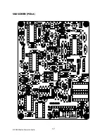
Page 17: ...SILKSCREEN PCB A 2020 Weston Precision Audio 17...
Page 18: ...SILKSCREEN PCB B 2020 Weston Precision Audio 18...
Page 19: ...SILKSCREEN PCB C 2020 Weston Precision Audio 19...


