


60
WHL-012 REV. 12.17.14
DIAGNOSTICS AND SUGGESTED CORRECTIVE ACTIONS
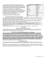
The appliance control is able to record information about the appliance
’s condition at the time of the five previous faults or errors. This
information is available to view in the Installer Mode under the History screen.
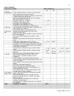
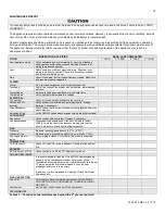
The following screens may be displayed when reviewing the appliance history. The table below also includes diagnostic information and
possible corrective actions.
Display
Condition
Diagnostic
Possible Corrective Actions
Nothing appears on
the display control
panel but the blower
runs at full speed
Control is not
receiving power
Check wiring for short circuit or
incorrect wiring
Correct wiring per wiring diagram including
connection of transformer to the control
Check transformer connection to the
control per wiring diagram. Check for
12V output of transformer
Replace transformer if it is receiving 120V, but
not outputting 12 VAC
Nothing appears on
the display control
panel and no other
appliance
components are
operating
Control is not
receiving 120V
power
Ensure service switch and/or circuit
breaker to appliance is turned ON
Turn on service switch or circuit breaker to
power appliance
Is there 120V at the service switch
Troubleshoot and correct the power supply to
the manual switch
Is the ON/OFF switch inside the
appliance cabinet is turned on
Turn ON the manual power switch inside the
appliance cabinet
Check for 120V at the line voltage
terminal block located inside the
appliance cabinet
Correct wiring inside the appliance cabinet
using the wiring diagram in the installation
manual
Inspect the fuse. Replace as
necessary
Replace the fuse with the proper part found in
the replacement part section of this manual. If
fuse blows again, recheck the wiring per
diagram
Nothing appears on
the display control
panel, but the
appliance is
operating
Occurs when
communications is
lost from the control
to the display
Check for loose connections and
proper pin alignment / engagement
on the control’s plug
Check for continuity on the wire harness from
the display to the control. See repair parts
section for proper replacement part.
Cycle power off and on using
appliance power switch and check for
operation
Replace with new display module. See repair
parts section for proper replacement part.
Table 27
–Diagnostics and Suggested Corrective Actions
PART 14 – ANNUAL MAINTENANCE PROCEDURES
The appliance must be inspected and serviced annually, preferably at the start of the heating season, by a qualified service technician.
In addition, the maintenance and care of the appliance as outlined in this manual must be performed by the user/owner to assure
maximum efficiency and reliability. Follow the maintenance procedures given throughout this manual. Failure to perform the service and
maintenance or follow the directions in this manual could damage the appliance or system components, resulting in substantial property
damage, severe personal injury, or death.
Check the Surrounding Area
To prevent the potential of substantial property damage, severe personal injury, or death, eliminate all the materials listed in Table 7
from the area surrounding the appliance and the vicinity of the combustion air intake. If contaminates are found:
Remove products immediately from area.
If contaminates have been there for an extended period, call a qualified service technician to inspect the appliance for possible
damage from acid corrosion.
If products cannot be removed, immediately call a qualified service technician to re-pipe the combustion air intake piping away from the
contaminated areas.
Combustible/Flammable Materials
Do not store combustible materials, gasoline, or other flammable vapors or liquids near the appliance. If found, remove these materials
immediately.
Air Contaminates
If allowed to contaminate combustion air, products containing chlorine or fluorine will produce acidic condensate that will cause
significant damage to the appliance. Read the list of potential contaminates and areas likely to have these contaminates in Table 7. If
any of these contaminates are in the room where the appliance is located, or combustion air is taken from one of the areas listed, the
contaminates must be removed immediately or the intake pipe must be relocated to another area.
Summary of Contents for WBRCLP140F
Page 2: ...2 WHL 012 REV 12 17 14 ...
Page 38: ...38 WHL 012 REV 12 17 14 Figure 26 Electrical Wiring Diagram ...
Page 39: ...39 WHL 012 REV 12 17 14 Figure 27 Ladder Diagram ...
Page 73: ...73 WHL 012 REV 12 17 14 ...
Page 74: ...74 WHL 012 REV 12 17 14 ...