


82
WHL-016 REV. 12.18.14
Do not install the condensate assembly if a component is lost or missing. Replace the entire assembly. Failure to follow this warning
could result in property damage, serious personal injury, or death.
6. Fill the condensate trap with fresh water prior to reassembly on the boiler.
7. Slide the condensate trap adapter onto the drain tube until the holes line up with the groove.
8. Insert stainless steel hitch pin to lock condensate adapter to the drain tube.
9. Reattach the clear plastic hose to the hose barb.
Do not operate the boiler without the clear hose attached from the hose barb to the pressure switch. Failure to follow this warning could
result in property damage, serious personal injury, or death.
10. If a condensate neutralizer kit is installed with the boiler, check the assembly when cleaning the condensate trap, and replenish the
limestone chips if necessary. When replacing the limestone chips, take care to ensure chips are
no smaller than ½” to avoid blockage in
condensate piping (for piping details, refer to condensate neutralizer installation instruction.)
11. Check condensate piping for sagging and/or leakage. Repair any sags or leaks before restoring power to the boiler.
It is very important that the condensate piping be no smaller than ½”. To prevent sagging and maintain pitch, condensate piping should
be
supported with pipe supports, and pitched ¼” per foot to allow for proper drainage.
The condensate line must remain unobstructed, allowing free flow of condensate. If condensate freezes in the line, or if line is
obstructed in any other manner, condensate can exit from the tee, resulting in potential water damage to property.
12. If the boiler has a condensate pump, ensure the pump operates properly before considering maintenance complete.
Summary of Contents for WBCNG399W
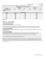
Page 14: ...14 WHL 016 REV 12 18 14 SPECIFICATIONS AND DIMENSIONS Figure 2 Specifications and Dimensions ...
Page 24: ...24 WHL 016 REV 12 18 14 Figure 8 Piping Symbol Legend ...
Page 59: ...59 WHL 016 REV 12 18 14 Figure 32 Cascade Master and Follower Wiring ...
Page 60: ...60 WHL 016 REV 12 18 14 Figure 33 Internal Connection Diagram LP 293 J ...
Page 83: ...83 WHL 016 REV 12 18 14 055 080 110 PARTS BREAKDOWN Figure 36 Replacement Parts LP 387 J ...
Page 85: ...85 WHL 016 REV 12 18 14 155 199 285 399 PARTS BREAKDOWN ...
Page 86: ...86 WHL 016 REV 12 18 14 Figure 38 Replacement Parts LP 387 KK ...
Page 87: ...87 WHL 016 REV 12 18 14 155 199 285 399 MODEL PARTS BREAKDOWN ...
Page 91: ...91 WHL 016 REV 12 18 14 ...
Page 92: ...92 WHL 016 REV 12 18 14 ...


