1.8. 33-125-lA
CAS-8 OPERATING MECHANISM
DESCRIPTION
The Type CAS-8 Operating Mechanism is equipped
with single coil shunt trip, an exhaust valve with
magnetic pilot, a magnetically operated pilot valve
for the automatic intake (this pilot valve can also be
operated manually by means of a pushbutton on top
of the magnet valve), an automatic throttle, a two
pole auxiliary switch, a ten pole auxiliary switch,
an operation counter, a control panel, an air com
pressor with storage tank, necessary heaters thermo
statically controlled, control equipment, and an all
steel weatherproof, outdoor housing which com
pletely encloses all of the above equipment.
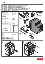
Figs. 1 and 2 show the mechanism in the closed
and latched position with the names of the various
parts. Referring to these figures, the breaker operat
ing rod is connected to the mechanism operating
lever, which is in turn connected to the piston which
operates in the cylinder of the compressed air
mechanism. The main lever is connected through a
link to the mechanism frame. This link allows
enough lateral motion for the piston and vertical pull
rod to keep their alignment throughout the opening
and closing stroke of the mechanism. The trip end
of the operating lever is held closed by a double
latch arrangement.
Caution:
The mechanism is not trip free
from the hand closing device.
Caution should
therefore be taken to make sure that the mechanism
control circuit and breaker disconnecting switches
are open when the mechanism is being operated by
hand, and also that the air supply to the mechanism
is shut off.
The mechanism and its associated equipment is
substantially constructed, and all vital parts such
as pins, pistons, valves, etc., are made of corrosion
resisting materials to insure satisfactory performance
over a long period of time. A 350-watt space heater
which is continuously energized reduces the con
densation of moisture in the housing. Two other
350-watt heaters operated by thermostatic control to
cut in at low temperatures are strategically located
to reduce the danger of moisture freezing around
the valves of the mechanism and compressor. The
compressor should not be started in freezing weather
without first making sure that the heaters have been
on long enough to thaw out valves, etc.-otherwise
the compressor may develop dangerously high
cylinder pressures. The compressor may be dis-
connected by opening the AB breaker in the motor
circuit, leaving the heaters energized.
The closing equipment consists of an air com
pressor with a storage tank and automatic control.
A pneumatic governor is set to maintain the pressure
in the storage tank at a certain value; the com
pressor motor is started when the pressure falls
approximately 15 lbs below this value. The normal
pressure may be set anywhere between 150 lbs
and 200 lbs, depending on the particular breaker
the mechanism is to be used with. Large breakers
will, of course, require higher pressure to close,
while it is desirable to limit the pressure to a lower
value on smaller breakers in order to prevent
undue slamming.
Compressor.
The air compressor is equipped
with a single phase, 60-cycle, 115/230 volt a-c
motor. The motor will be connected for 230 volts
when shipped in order to prevent damage to the
motor from over-voltage unless 115 volt connection
is specified. The air system will be suitable for at
least five operations without recharging. The
system will recharge from atmospheric pressure in
one hour or less. The pressure will build back to
normal after the motor has been started by the
pneumatic governor (15 lbs below normal) in
approximately 5 minutes. The storage tank fulfills all
requirements of State Inspection Codes and is
supplied with suitable accessories. All equipment is
manufactured under the ASME requirements and
receives underwriter inspection before shipment.
Safety Devices.
If anything should go wrong
with the compressor or air equipment so that normal
pressure is not maintained, a low pressure alarm and
cutout switch are provided for indication and pro
tection. The low pressure cutout switch is set to open
the closing control circuit before the pressure drops
too low to close the breaker satisfactorily. The low
pressure alarm switch is set 5 to 10 lbs above this
to close the circuit to the station alarm. A safety
valve is supplied on the storage tank which will pop
off at approximately 15% above the normal operat
ing pressure. This prevents the pressure from build
ing up to a dangerous level if the pneumatic
governor fails to cut off the compressor motor. The
settings of all pressure switches and safety valves
are made at the factory and should not be changed,
except to re-adjust if necessary to settings given on
nameplate mounted on inside of housing door.
3
www
. ElectricalPartManuals
. com