background image


LEONARDO PRO X 

User manual


EN


32 


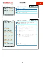
MENU 8.4 

WRD SETUP: 
Oper.Mode: 

MONITOR 

Backlight: 

auto OFF


RESET: 

RUN


UPDATE FW: 

RUN


Tech. Menu Psw: 

00


List displayed: 


Settable values and description:


Value: 


 <

0..FF

>: password to access the Technical Menu. 


*CAUTION* Technical Menu is reserved for factory checks.


RUN

 : *CAUTION* starts the procedure to update the firmware 

in 


the WBM device. The firmware update  file  must  be  present 


in the uSD card. 


To start the procedure press both keys ↑ and ↓.


 auto OFF; always ON

: LCD backlight, Auto-OFF or always ON. 


 MONITOR; CONTROLLER

: Operatimg Mode: Monitor o Controller.


PV values DC 

5


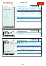
MENU 8.3 

W-INVERTER SETUP: 
 not present 


List displayed: 


Settable values and description:


Value: 


 Device not present. 

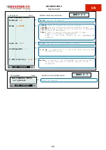
MENU 8.3 


˄


˄


Ubat GE Start: 

---


|


Ubat GE Hist: 

+8 V


RESET: 

RUN


UPDATE FW: 

---


List displayed: 

Settable values and description:


Value: 


RUN

  :  *CAUTION*  starts  the  procedure  to  update  the  firmware  in 

the WBM device. The firmware update  file  must  be  present 
in the uSD card.


 <

---..62  V

>:  In  Monitor  mode,  it  defines  the  voltage  threshold 


below  which  the  contact  for  switching  on  the  GE  is 


closed.


 RUN

 : Resets the W-INVERTER.


 <

+8..+11 V

>: In Monitor mode, it defines the hysteresis voltage 


to  be  added  to  GE  start,  to  obtain  the  voltage  threshold 


above  which  the  contact  for  switching  on  the  GE  is 


reopened.


Summary of Contents for Leonardo PRO X

Page 1: ...Leonardo PRO X Manuale utente User manual IT EN ...

Page 2: ......

Page 3: ...otovoltaica anche in caso di blackout e un uscita ausiliaria per l accensione di un carico che permette il massimo autoconsumo In caso di blackout della rete elettrica il Leonardo PRO X alimenta le utenze collegate all uscita EPS con un tempo di ripristino inferiore ai 10 ms È possibile abbinare al Leonardo PRO X la versione slave per espandere la potenza disponibile e o per gestire impianti trifa...

Page 4: ...ica e prendere appuntamento telefonico per l assistenza da remoto Controllare prima di accendere il dispositivo se la sorgente di tensione disponibile è conforme alle impostazioni di configurazione del prodotto come descritto nel manuale Installare il prodotto in un ambiente che garantisca il range operativo di temperatura Assicurarsi che non ci siano sostanze chimiche parti in plastica tende o al...

Page 5: ...elementi dell imballo cartone cellophane punti metallici nastro adesivo reggette ecc possono tagliare e o ferire se non maneggiati con cura I componenti dell imballo vanno eliminati e smaltiti secondo le norme vigenti nel paese di installazione All apertura dell imballo controllare l integrità dell apparecchiatura e verificare la presenza di tutti i componenti Qualora si riscontrino difetti o dete...

Page 6: ...one All apertura dell imballo controllare l integrità dell apparecchiatura e verificare la presenza di tutti i componenti Qualora si riscontrino difetti o deterioramenti sospendere le operazioni e interpellare il vettore nonché informare tempestivamente il Service Western Elenco componenti forniti All interno dell imballo vengono forniti i seguenti componenti necessari alla corretta installazione ...

Page 7: ...Configurazione DC 14 2 2 6 Collegamento Regolatori Di Carica WRM SOLO Configurazione DC 15 2 2 7 Installazione del LEONARDO PRO X SL 15 2 2 7 1 Connessioni lato AC 16 2 2 7 2 Connessioni lato DC 16 2 2 7 3 Connessione VE BUS 17 3 AVVIO DEL SISTEMA 17 4 DISPLAY INTEGRATO WRD 18 4 1 Interfaccia Utente 19 4 1 1 Navigazione Menu 19 4 1 2 Basic Advanced 20 4 1 3 System Setup 20 4 1 4 Date Time Setup 20...

Page 8: ...36 7 1 1 Inserimento PLANT KEY 37 7 1 2 Inserimento dati 37 7 2 Monitoraggio di un impianto 38 7 2 1 Monitoraggio tramite APP my Leonardo 39 7 2 1 1 Monitoraggio e Controllo WE Box per veicoli elettrici 39 8 CARATTERISTICHE ELETTRICHE 41 9 GARANZIA DI LEGGE 42 10 SMALTIMENTO DEI RIFIUTI 42 APPENDICE in fondo al manuale ...

Page 9: ...rodotta dall impianto FV L energia in esubero sarà direttamente immessa in rete in modalità FEED IN Per impianti fotovoltaici in configurazione DC è possibile disattivare l immissione in rete ZERO FEED IN ed è disponibile un contatto pulito per il massimo autoconsumo per attivare carichi domestici scaldabagno pompa di calore ecc aumentando la propria quota di energia auto consumata 5 Di notte o qu...

Page 10: ... parallelo con la rete On Grid è responsabile dello sgancio della rete in caso di parametri fuori specifica tensione e frequenza 3 WRD è il sistema integrato di acquisizione dei dati per monitoraggio ed impostazione da remoto se opportunamente connesso ad Internet 4 Energy Manager determina il set point per la potenza di carica e scarica in funzione della produzione dell impianto FV esistente e de...

Page 11: ...intorno del dispositivo che ne permette il raffreddamento per convezione forzata dell aria 2 Fissare a muro la staffa di supporto tramite i tasselli e le viti forniti in dotazione successivamente agganciare l inverter tramite la piastra posta nella parte superiore dell apparecchio Infine fissare l inverter alla parete utilizzando i fori predisposti nella parte inferiore dell apparecchio Il tutto c...

Page 12: ...ia RJ10 Ethernet Connessione alla rete internet RJ45 Morsettiera per il collegamento interno del contatto di massimo autoconsumo Uscita contatto per attivazione carichi ausiliari in caso di installazione DC con regolatori esterni Led di segnalazione 2 2 1 Collegamento rete di distribuzione lato AC Il Leonardo PRO X 3000 48 è dotato di un uscita in corrente alternata AC OUT 1 ed una linea di ingres...

Page 13: ...modo da evitare falsi interventi In caso di impianti composti da più inverter collegati ad un unico interruttore con protezione differenziale è consigliata l installazione di un dispositivo che permetta la regolazione del valore di scatto e del tempo di intervento 2 2 2 Collegamento lato DC Effettuare il collegamento con la morsettiera BAT Collegare gli occhielli dei cavi batteria positivo rosso e...

Page 14: ...ASTER su Port 1 Batteria SLAVE su Port 0 3 impostare tutti gli switch di configurazione ADDRESS in posizione OFF in quanto non utilizzati 2 2 2 3 Batterie Midac ATTENZIONE Per configurazioni di batterie MIDAC RES 4 2 in parallelo e per tutte le altre informazioni fare riferimento al manuale di installazione delle batterie Configurazione con singola batteria RES 4 2 Collegare gli occhielli dei cavi...

Page 15: ...lo schema di installazione seguendo gli schemi di collegamento 1 2 3 4 e rispettando il verso della freccia il verso della freccia nello schema deve essere lo stesso del verso riportato sul sensore Massima lunghezza 20 m Fig Cablaggio sensore di corrente Fig 13 Cablaggio sensore di corrente 2 2 4 Installazione Contatore Controllo P1 SOLO Configurazione AC Il Contatore di controllo P1 prevede un co...

Page 16: ...ormale stato di funzionamento 2 2 5 Collegamento Contatto Massimo Autoconsumo SOLO Configurazione DC Nel caso in cui il Leonardo PRO X venga usato in configurazione DC è possibile utilizzare un contatto ausiliaro per attivare dei carichi pompa di calore scaldabagno ecc utilizzando la porta AUX RELAY La porta AUX RELAY AC nominale 230V 4A DC nominale 4A fino a 35VDC e 1A fino a 60VDC è utilizzabile...

Page 17: ... regolatore ID3 nel secondo regolatore e così via Per WRM60 X SL seguire i collegamenti in A5 utilizzando il cavo in dotazione Fare sempre riferimento ai manuali dei regolatori WRM30 WRM60 X per le connessioni di potenza e per le impostazioni degli indirizzi 2 2 7 Installazione del LEONARDO PRO X SL È possibile espandere il proprio impianto installando un LEONARDO PRO X SL Il Leonardo PRO X SL vie...

Page 18: ...ONARDO PRO X Manuale utente IT 16 2 2 7 1 Connessioni lato AC Fig 18 Schemi di connessione AC del Leonardo PRO X SLAVE 2 2 7 2 Connessioni lato DC Fig 19 Schemi di connessione DC del Leonardo PRO X SLAVE ...

Page 19: ...anno richieste fare riferimento a 4 DISPLAY INTEGRATO a Dalla Home tenere premuti simultaneamente le due frecce DOWN UP per entrare nel menu 7 3 Utilizzando la freccia UP per spostarsi nel menu 7 4 SYSTEM INFO Tenere premuto per entrare in edit mode dei parametri Utilizzando DOWN spostarsi fino al campo U I Mode premere ENTER e poi DOWN per impostare il valore su Advanced Tenere premuto ENTER per ...

Page 20: ...enu 8 3 W INVERTER Tenere premuto ENTER per entrare in edit mode dei parametri Premere nuovamente ENTER Utilizzando i tasti DOWN e UP selezionare il System Type 7 e impostare gli altri parametri in accordo con la configurazione voluta vedi tabella A8 in Appendice Tenere premuto ENTER per confermare Informazioni aggiuntive le trovate nel paragrafo successivo g Tenendo premuto il tasto ESC torniamo ...

Page 21: ...remere il tasto UP in modo da far apparire e quindi tenere premuto per 1 sec il tasto OK Fig 21 Menu di navigazione È possibile entrare nella modalità EDIT Fig 22 laddove è concesso per modificare i parametri della videata mantenendo premuto per 1 sec il tasto EDIT L entrata nella modalità EDIT è visibile sul display dalla presenza dei cursori sul parametro modificabile Per la selezione del parame...

Page 22: ...n funzione della configurazione corrente Le spiegazioni dettagliate sono descritte nel capitolo Configurazioni 4 1 4 Date Time Setup Nel menu 7 1 DATE TIME si imposta l orologio di sistema e il fuso orario Timezone È importante impostare correttamente quest ultimo parametro con il Timezone del sito dove è collocato l impianto in maniera che l aggiornamento dell orologio da remoto possa avvenire co...

Page 23: ...voltaico AC Valori fotovoltaico DC 5 Corrente da PV AC Potenza PV DC Potenza PV AC DC MENU 2 0 Barra di stato Tensione di sistema Temperatura di batteria A Controllo di Sistema in esecuzione B Tensione di Low battery Tensione di Batteria A Fase di carica Bulk Abs Float Tensione di fine carica indicatore tensione di batteria A Flash se fuori range B PAUSE carica in pausa Barra di stato Carica o sca...

Page 24: ...et dei contatori del WBM2 n Menu Warning Data del Reset dei contatori dei WRM1 contatore di batteria OUT dal Reset MENU 4 X stringa PV A stringa PV B n Menu Warning Tensione stringa PV1 Corrente stringa PV1 Potenza stringa PV1 Ingresso PV visualizzato Temperatura interna dell hardware PV A Temperatura interna dei PV charger 6 A Flash if out of range MENU 3 3 LEONARDO 4 3 PHASE Valori delle 3 fasi ...

Page 25: ...orso Beep Warning in corso Beep Numero Menu per 4 sec Stato connessione cloud On Line Off Line Activity Abilitazione alla carica o scarica Flash se in modulazione 4 MENU 6 0 Evento più vecchio occorso Evento più recente occorso Numero progressivo degli eventi 1 32 Filtro della lista di eventi n Menu Warning Data e ora evento codice Evento tipo di Evento ...

Page 26: ...scita LOAD è disattivata 5 24h 24h uscita LOAD sempre attiva 5 1 16h uscita LOAD attiva dal tramonto per le ore impostate 5 Only Night uscita LOAD attiva solo durante la notte 5 Only Day uscita LOAD attiva solo durante il giorno 5 OnSurPlus uscita LOAD attiva solo durante un eccedenza di energia 5 Elenco visualizzato Valori impostabili e descrizioni Valore 0 ON disch sotto questa soglia l uscita A...

Page 27: ...za NOT PRESENT e non ci sono informazioni disponibili uSD CARD legge il tipo di file system NONE FAT12 16 32 e calcola lo spazio libero sulla uSD FIND WRD legge ed elenca uno alla volta i file mostrando nome dimensione e data dell ultimo aggiornamento Al termine mostra END LIST SAMPLE EVENT mostra il tempo rimanente per il prossimo campionamento Elenco visualizzato Valori impostabili e descrizioni...

Page 28: ...4 secon DNS 255 OFF ON Disabilita Abilita la connessione al cloud per il trasferimento dei dati al server 0 255 imposta l indirizzo IP del dispositivo 0 255 0 255 1 255 DHCP impostazione di rete automatica gli altri valori verranno ignorati 0 255 imposta la sottomaschera di rete 0 255 0 255 0 255 0 255 imposta l indirizzo IP del Gateway 0 255 0 255 0 255 0 255 imposta l indirizzo IP del DNS primar...

Page 29: ...4 0 0 WRMxx n 24 0 0 U I Mode Basic OFF LINE ON LINE stato corrente della conness cloud Elenco visualizzato Valori impostabili e descrizioni Valore revisione firmware dei dispositivi WRMxx dal 1 al 24 0 0 se non presente indirizzo IP corrente sottomaschera di rete corrente indirizzo IP del Gateway corrente indirizzo IP del DNS primario corrente indirizzo IP del DNS secondario corrente indirizzo MA...

Page 30: ...4 00 WRMxx n 24 00 RUN avvia la procedura automatica per rilevare gli indirizzi dei dispositivi connessi Elenco visualizzato Valori impostabili e descrizioni Valore 00 33 Indirizzo WBUS del dispositivo WBM 0 32 Indirizzo WBUS dei dispositivi WRMxx dal 1 al 24 00 se non presente 00 34 Indirizzo WBUS del dispositivo W INVERTER MENU 8 0 ...

Page 31: ...h 100 sopra questa soglia l uscita ALARM 1 è disattivata Scarica ON ON charge 100 sopra questa soglia l uscita ALARM 2 è attivata Carica OFF 0 ON charge sotto questa soglia l uscita ALARM 2 è disattivata Carica ON no smart battery Pb Flood 14 80 25 C 29 60 25 C 59 20 25 C Impostazione per operare con batteria di tipo Pb Flood acido libero Pb Seal Gel 14 40 25 C 28 80 25 C 57 60 25 C Impostazione p...

Page 32: ... la procedura di aggiornamento firmware nel dispositivo WRM30 Il file di aggiornamento deve essere presente nella uSD 1 24 seleziona il WRMxx da editare auto VEoC 0 2 0 4 0 8V 12 72 13 68V 25 44 27 36V 50 88 54 72V sopra questa soglia il WRMxx esce dallo stato di Low Battery e riattiva il LOAD 2 00V 3 28V 4 56V 5 84V sotto questa soglia il WRM30 rileva il tramonto auto parall indep modo in cui l a...

Page 33: ...oppure la voce MeterPort è impostata al valore Genset definisce la potenza con cui caricare il banco batterie Definisce l utilizzo della porta MeterPort sul W INVERTER Porta non utilizzata PV Pulse Porta in Input per collegare il meter impulsivo della produzione fotovoltaica on grid Genset Porta in output si attiva quando la percentuale della batteria scende sotto la soglia di OFF disch 1 E rester...

Page 34: ... CONTROLLER Modo Operativo Monitor o Controller MENU 8 3 W INVERTER SETUP not present Elenco visualizzato Valori impostabili e descrizioni Valore Dispositivo non presente MENU 8 3 Ubat GE Start Ubat GE Hist 8 V RESET RUN UPDATE FW Elenco visualizzato Valori impostabili e descrizioni Valore RUN ATTENZIONE avvia la procedura di aggiornamento del firmware del dispositivo W Inverter Il file di aggiorn...

Page 35: ...è connesso prima o dopo il punto di lettura del sensore TA o del W INVERTER 0 25 kW Potenza prelevata dalla rete destinata all EV in modalità 3 FAST 0 GREEN All EV viene fornita la potenza PV in eccesso 1 PVonEV All EV viene fornita la potenza PV disponibile 2 BatBOOST All EV viene fornita la potenza PV disponibile sommata alla potenza del W INVERTER in eccesso 3 FAST All EV viene fornita la poten...

Page 36: ...nfigurazione DC verificare la produzione direttamente sui display dei regolatori di carica la batteria è in carica se il consumo è inferiore alla produzione Verificare anche lo stato dei led della batteria 5 2 Scarica Della Batteria Per effettuare la prova di scarica della batteria occorre attendere che l indicatore di scarica sia abilitato Spegnere l impianto fotovoltaico e verificare che la batt...

Page 37: ...SO n 4 lampeggi ogni 10 Secondi stato di allarme INVERTER INTEGRITA DATI Tab 3 Tabella di segnalazione LED 6 2 Risoluzione Problemi Problema Causa Risoluzione Spia On grid spenta e simbolo della rete AC IN sul display lampeggiante Assenza di tensione AC su AC IN Verificare la tensione in ingresso e il cablaggio AC IN del Leonardo PRO X Assenza tensione in uscita AC OUT Assenza di tensione AC su AC...

Page 38: ... a resettare l inverter Verificare l integrità di eventuali fusibili DC di protezione Se il problema permane si consiglia di contattare l assistenza tecnica Western CO Tab 4 Tabella risoluzione problemi 7 my Leonardo Il sistema di accumulo Leonardo PRO X può essere monitorato e controllato attraverso il portale web e app my Leonardo Le funzioni più importanti offerte dal my Leonardo sono monitorag...

Page 39: ...anco sinistro del prodotto Fig 25 Inserimento Plant Key 7 1 2 Inserimento dati Nella schermata successiva l installatore deve inserire alcuni dati anagrafici obbligatori riguardanti l impianto ulteriori dati verranno automaticamente compilati dal sistema N B Tutti i dati anagrafici potranno essere modificati in un secondo momento Fig 26 Inserimento dati impianto ...

Page 40: ...ione di un impianto sul portale 7 1 Dopo aver effettuato l accesso sarà presente una lista dei propri impianti disponibile in versione mappa griglia ed elenco Fig 27 Monitoraggio impianto Inoltre da questa schermata è possibile accedere alle impostazioni del proprio account e ad alcune preferenze del portale Nella sezione impostazioni è possibile attivare le notifiche Cliccando su un impianto è po...

Page 41: ...ione 7 1 e di monitoraggio 7 2 7 2 1 1 Monitoraggio e Controllo WE Box per veicoli elettrici Monitoraggio potenza istantanea Tramite l indicatore a mostrato in Fig 29 è possibile visualizzare la potenza istantanea caricata sul veicolo elettrico Il valore è espresso in kW Fig 29 Visualizzazione potenza istantanea N B La potenza caricata nel veicolo elettrico viene anche inclusa nell indicatore dei ...

Page 42: ...profili di carica seguenti Profilo Potenza Caricata Veicolo Elettrico 1 Green Fotovoltaico carichi domestici 2 PV on EV Fotovoltaico 3 Battery Boost Fotovoltaico Potenza nominale dell inverter 4 Fast Fotovoltaico Potenza nominale inverter Contatore di rete vedi impostazioni menu 8 5 carichi domestici Tab 5 Profili di ricarica veicoli elettrici N B In caso di installazioni in configurazione DC del ...

Page 43: ... Topology Top Toroidal isolation transformer Toroidal isolation transformer Cooling Ven Forced ventilation Forced ventilation PV production meter Mis 40A with direct connection 40A with direct connection Consumption current sensor Ta 100A split core current transformer 100A split core current transformer AC CHARGER Maximum charge power Pch 2 1kW 3 5kW Maximum charge current Ich 35A 70A Maximum eff...

Page 44: ...causa di naturale logoramento che presentino guasti causati da imperizia o negligenza del cliente da imperfetta installazione da manomissioni da erronea manutenzione dell impianto o interventi diversi dalle istruzioni da noi fornite La garanzia decade altresì in caso di danni derivanti da trasporto e o cattiva conservazione del prodotto causa di forza maggiore o eventi catastrofici gelo per temper...

Page 45: ... guarantees photovoltaic production even in case of blackouts and an auxiliary output for a load that allows maximum self consumption to be switched on In the event of a blackout the Leonardo PRO X powers the utilities connected to the EPS output with a recovery time of less than 10 ms Slave version can be combined with Leonardo PRO X to expand the available power and or to manage three phase syst...

Page 46: ...ssistance and make a telephone appointment for remote assistance Before turning on the device check whether the available power source complies with the product configuration settings as described in the manual Install the product in an environment that ensures the operating temperature range Make sure that there are no chemicals plastic parts curtains or other fabrics that can ignite nearby the e...

Page 47: ...at the packaging cardboard cellophane staples adhesive tape straps etc can cut and or injure if not handled with care The packaging components must be disposed of in accordance with the regulations in force in the country of installation When opening the packaging check the integrity of the equipment and check that all components are present If defects or deteriorations are found suspend operation...

Page 48: ...ce in the country of installation When opening the packaging check the integrity of the equipment and check that all components are present If defects or deteriorations are found suspend operations and contact the carrier and promptly inform the Western Service List of components provided The following components are supplied in the packaging which are necessary for the correct installation of the...

Page 49: ...mption Contact DC Configuration ONLY 14 2 2 6 Connecting WRM Charge Regulators DC Configuration ONLY 15 2 2 7 LEONARDO PRO X SL Installation 15 2 2 7 1 AC side connections 16 2 2 7 2 DC side connections 16 2 2 7 3 VE BUS connection 17 3 SYSTEM START UP 17 4 INTEGRATED DISPLAY WRD 18 4 1 USER INTERFACE 19 4 1 1 Menu Navigation 19 4 1 2 Basic Advanced 20 4 1 3 System Setup 20 4 1 4 Date Time Setup 2...

Page 50: ...tallers 36 7 1 1 Entering the PLANT KEY 37 7 1 2 Data entry 37 7 2 Monitoring a system 38 7 2 1 Monitoring via APP my Leonardo 39 7 2 1 1 WE Box Monitoring and Control for Electric Vehicles 39 8 ELECTRICAL CHARACTERISTICS 41 9 LEGAL WARRANTIES 42 10 WASTE DISPOSAL 42 APPENDIX at the end of the manual ...

Page 51: ...nergy directly produced by the PV plant The excess energy will be directly fed into the grid in FEED IN mode For photovoltaic plants in DC configuration it is possible to deactivate the grid feed in ZERO FEED IN and a potential free contact is available for maximum self consumption to activate domestic loads water heater heat pump etc increasing its share of self consumed energy 5 At night or when...

Page 52: ...1kW 2 Input relay connects the inverter in parallel with the On Grid mains it disconnects the grid in case of off specification parameters voltage and frequency 3 WRD the integrated data acquisition system for remote monitoring and setting if properly connected to the Internet 4 Energy Manager determines the set point for charging and discharging power according to the production of the existing P...

Page 53: ...n such a way as to leave an obstacle free space of at least 10cm around the device that allows for forced air convection cooling 2 Fix the support bracket to the wall using the dowels and screws supplied then hook the inverter using the plate at the top of the unit Lastly secure the inverter to the wall using the holes at the bottom of the unit All as shown in Pic 3 Pic 3 Wall mounting Install the...

Page 54: ...ices WRM WBM RJ11 CAN CANBUS battery connection RJ10 Ethernet Internet connection RJ45 Terminal block for internal connection of the maximum self consumption contact Contact output for activating auxiliary loads in case of DC installation with external regulators Warning LED 2 2 1 Distribution grid connection AC side The Leonardo PRO X is equipped with an AC OUT 1 alternating current output and an...

Page 55: ... thermal magnetic circuit breaker with 300 mA tripping current in order to avoid false tripping In the case of systems consisting of several inverters connected to a single switch with differential protection it is recommended to install a device that allows the trip value and tripping time to be adjusted 2 2 2 DC side connection Make the connection with the BAT terminal block Connect the eyelets ...

Page 56: ...NK cable MASTER battery on Port 1 SLAVE battery on Port 0 3 set all ADDRESS configuration switches to the OFF position as they are not used 2 2 2 3 Midac Batteries ATTENTION For configurations of MIDAC RES 4 2 batteries in parallel and for all other information refer to the battery installation manual Configuration with single RES 4 2 battery Connect the eyelets of the battery cables positive red ...

Page 57: ...following the connection diagrams 1 2 3 4 and respecting the direction of the arrow the direction of the arrow in the diagram must be the same as the direction shown on the sensor Maximum length 20 m Fig Cablaggio sensore di corrente Pic 13 Current sensor wiring 2 2 4 Control Meter P1 Installation AC Configuration ONLY Control Meter P1 provides a direct connection of the AC power cables of the exi...

Page 58: ...ormal operating state 2 2 5 Connection of the Maximum Self Consumption Contact DC Configuration ONLY If the Leonardo PRO X is used in DC configuration an auxiliary contact can be used to activate loads heat pump water heater etc using the AUX RELAY port The AUX RELAY port AC rated 230V 4A DC nominal 4A up to 35VDC and 1A up to 60VDC can be used to activate an external relay installed in the electr...

Page 59: ...D2 in the first regulator ID3 in the second regulator and so on For WRM60 X SL follow the connections in A5 using the supplied cable Always refer to the WRM30 WRM60 X controllers manuals for power connections and address settings 2 2 7 LEONARDO PRO X SL Installation It is possible to expand your system by installing LEONARDO PRO X SL Leonardo PRO X SL is used either to expand a single phase system...

Page 60: ...LEONARDO PRO X User manual EN 16 2 2 7 1 AC side connections Pic 18 Leonardo PRO X SLAVE AC Connection Diagram 2 2 7 2 DC side connections Pic 19 Leonardo PRO X SLAVE DC Connection Diagram ...

Page 61: ... move to the 7 4 SYSTEM INFO menu Press and hold to enter settings in edit mode Using DOWN move to the U I Mode field press ENTER and then DOWN to set the value to Advanced Press and hold ENTER to confirm b Press the DOWN key to move to the 7 0 SYSTEM menu Press ENTER and hold to enter settings in edit mode Press ENTER again and use the DOWN and UP keys to select the type of battery installed You ...

Page 62: ...select the System Type 7 and set the other parameters according to the desired configuration see A8 table in Appendix Press and hold ENTER to confirm additional information can be found in the next paragraph g By holding down the ESC key we return to menu 7 0 Using the UP key return to the 7 4 SYSTEM INFO menu and set the U I Mode field to Basic as done in point a Press and hold ENTER to confirm h...

Page 63: ...d Setup item on the 7 5 OTHERS screen press the UP botton so that appears and then press the OK button for 1 sec Pic 21 Navigation Menu It is possible to enter the EDIT mode Pic 22 where it is allowed to modify the parameters by keeping pressed the EDIT button for 1 sec Entry into the EDIT mode is visible on the display by the presence of the cursors on the modifiable parameter For editing are use...

Page 64: ...to the current configuration Detailed explanations are described in the chapter Configurations 4 1 4 Date Time Setup In the menu 7 1 DATE TIME you set the system clock and the time zone Timezone It is important to correctly set this last parameter with the Timezone of the place where the system is located so that the remote clock can be updated correctly 4 1 5 Data Logger Setup In the menu 7 2 DAT...

Page 65: ... PV values AC PV values DC 5 PV current AC PV power DC PV power AC DC MENU 2 0 Status bar System voltage Battery temperature A System Control currently running B Voltage of Low battery Battery voltage A Charging phase Bulk Abs Float End of charge voltage Battery voltage indicator A Flash if out of range B PAUSE charge paused Status bar Battery charge or discharge DC B State of charge A Home consum...

Page 66: ... of the WBM meters 2 n Menu Warning Reset date of the WRM meters 1 Battery OUT meter from Reset MENU 4 X PV string A PV string B n Menu Warning PV string voltage 1 PV string current 1 PV string power 1 PV input displayed Internal temperature of the PV hardware A Internal temperature of the PV charger 6 A Flash if out of range MENU 3 3 LEONARDO 4 3 PHASE Values of the 3 phases referred to the inver...

Page 67: ...s Error in progress Beep Warning in progress Beep Menu number for 4 sec Cloud connectione status On Line Off Line Activity Enabled for charging o discharging Flash if in modulation 4 MENU 6 0 Oldest event occurred Most recent event Progressive number of event 1 32 Event list filter n Menu Warning Event date time Event code Type of Event ...

Page 68: ...D is deactived 5 24h 24h LOAD output always active 5 1 16h LOAD output active from sunset for the set hours 5 Only Night LOAD output active only during the night 5 Only Day LOAD output active only during the day 5 OnSurPlus LOAD output active only during energy surplus 5 List displayed Settable values and description Value 0 ON disch below this threshold the ALARM 1 output is actived Discharging O...

Page 69: ...card show NOT PRESENT and no information is available uSD CARD read the type of file system NONE FAT12 16 32 and calculates the free space on the card FIND WRD read and list the files one at a time by showing the name size and date of the last update At the end shows END LIST SAMPLE EVENT show the remaining time for the next sampling List displayed Settable values and description Value MENU 7 1 Se...

Page 70: ...DNS 255 2 secon DNS 255 3 secon DNS 255 4 secon DNS 255 OFF ON Disable Enable cloud connection to transfer data to the server 0 255 set the device IP Address 0 255 0 255 1 255 DHCP set the Network Setup automatically the other values will be ignored 0 255 set the subnet mask 0 255 0 255 0 255 0 255 set the Gateway IP Address 0 255 0 255 0 255 0 255 set the primary DNS IP Address 0 255 0 255 0 255 ...

Page 71: ...0 WRMxx n 2 1 0 WRMxx n 3 0 0 WRMxx n 4 0 0 WRMxx n 24 0 0 U I Mode Basic OFF LINE ON LINE current status of cloud connection List displayed Settable values and description Value firmware revision of the WRMxx devices from 1 to 24 0 0 if not present current device IP Address current subnet mask current Gateway IP Address current primary DNS IP Address current secondary DNS IP Address device MAC Ad...

Page 72: ... WRMxx n 4 00 WRMxx n 24 00 RUN starts the automatic procedure to detect the addresses of the connected devices List displayed Settable values and description Value 00 33 WBUS Address of the WBM device 0 32 WBUS Address of the WRMxx device from 1 to 24 00 if not present 00 34 WBUS Address of the W INVERTER device MENU 8 0 ...

Page 73: ...4 40 25 C 28 80 25 C 57 60 25 C Setting to operate with battery type Pb Seal or Gel LiFePO4 14 00 14 70V fixed 28 00 29 40V fixed 56 00 58 80V fixed Setting to operate with battery type Lithium with integrated BMS smart battery 4 1 LG Chem RESU 57 60 fixed LG CHEM RESU smart battery setting 2 PYLONTECH 54 00 fixed Pylontech smart battery setting 3 MIDAC 59 00 fixed MIDAC smart battery setting 10 2...

Page 74: ...TION starts the procedure to update the firmware in the WBM device The firmware update file must be present in the uSD card 1 24 select te WRMxx to edit auto VEoC 0 2 0 4 0 8V 12 72 13 68V 25 44 27 36V 50 88 54 72V above this threshold the WRMxx goes out Low Battery status and reactivates the LOAD 2 00V 3 28V 4 56V 5 84V below this threshold the WRMxx detects the sunset auto parall indep mode in w...

Page 75: ...ing fields 25 5 kW If the Max Pw Grid item is set or the MeterPort item is set to the Genset value it defines the power with which to charge the battery bank Defines the use of the MeterPort port on the W INVERTER Port not used PV Pulse Input Port to connect the pulse meter of on grid PV production Genset Output Port it is activated when the battery percentage falls below the OFF disk 1 threshold ...

Page 76: ...ROLLER Operatimg Mode Monitor o Controller PV values DC 5 MENU 8 3 W INVERTER SETUP not present List displayed Settable values and description Value Device not present MENU 8 3 Ubat GE Start Ubat GE Hist 8 V RESET RUN UPDATE FW List displayed Settable values and description Value RUN CAUTION starts the procedure to update the firmware in the WBM device The firmware update file must be present in t...

Page 77: ...s if the CAR CHARGER is connected before or after the reading point of the TA sensor or of the W INVERTER 0 25 kW In 3 FAST mode it is the power taken from the grid destined for the EV 0 GREEN The EV is supplied with excess PV power 1 PVonEV The EV is supplied with the available PV power 2 BatBOOST The EV is supplied with the available PV poweradded to the excess W INVERTER power 3 FAST The EV is ...

Page 78: ...e battery is charging if consumption is lower than production Also check the status of the battery LEDs 5 2 Battery Discharge To perform the battery discharge test wait until the discharge indicator is enabled Switch off the photovoltaic system and check that the battery starts to discharge to deliver energy to the loads check also the status of the battery LEDs grid withdrawals are minimised 5 3 ...

Page 79: ...ator light off and AC IN grid symbol on display flashing No AC voltage on AC IN Check the input voltage and the AC IN wiring of the Leonardo PRO X No AC OUT output voltage No AC voltage on AC IN and BAT connectors STATUS LED off Check the connection of the VE Bus cable Check the connection of the VE BUS cable internal control bus Led CHARGER always off PV On Grid type systems Deactivated AC Charge...

Page 80: ... DC fuses If the problem persists please contact Western CO Technical Assistance Tab 4 Troubleshooting table 7 my Leonardo The Leonardo PRO X storage system can be monitored and controlled through my Leonardo web portal and app The most important functions offered by my Leonardo are real time monitoring and display of your storage system history remote access to the device display warnings and rep...

Page 81: ...eft side of the product must be entered in the appropriate box Pic 25 Entering Plant Key 7 1 2 Data entry On the next screen the installer must enter some mandatory master data concerning the system further data will be automatically filled in by the system N B All personal data can be changed later Pic 26 Entering System Data ...

Page 82: ...lowing the guide in paragraph Registering a system on the portal 7 1 After logging in there will be a list of your systems available in map grid and list version Pic 27 System Monitoring In addition from this screen you can access your account settings and some portal preferences In the settings section you can activate notifications By clicking on a system you can access the dashboard where three...

Page 83: ...ame registration 7 1 and monitoring 7 2 steps 7 2 1 1 WE Box Monitoring and Control for Electric Vehicles Instant power monitoring Through the indicator a showed in Pic 29 it is possible to monitor the instantaneous EV Charge Power The value is showed in kW Pic 29 Instant power display N B The EV charge power is also included in the value showed in the home loads indicator a 5 72 kW 5 72 kW ...

Page 84: ... the difference between the four charge profiles Profile EV Charge Power 1 Green Photovoltaic home Loads 2 PV on EV Photovoltaic 3 Battery Boost Photovoltaic Inverter Rated Power 4 Fast Photovoltaic Inverter Rated Power Grid power see settings in menu 8 5 home loads Tab 5 Electric vehicle charging profiles N B In case of installations with Leonardo PRO X DC configuration the maximum EV charge powe...

Page 85: ...ology Top Toroidal isolation transformer Toroidal isolation transformer Cooling Ven Forced ventilation Forced ventilation PV production meter Mis 40A with direct connection 40A with direct connection Consumption current sensor Ta 100A split core current transformer 100A split core current transformer AC CHARGER Maximum charge power Pch 2 1kW 3 5kW Maximum charge current Ich 35A 70A Maximum efficie...

Page 86: ...iscretion are defective due to natural wear and tear failures caused by inexperience or negligence on the customer s end imperfect installation tampering incorrect maintenance of the system or interventions other than the instructions provided by us The warranty is also forfeited in the event of damage resulting from transport and or poor conservation of the product force majeure or catastrophic e...

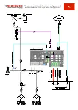
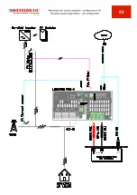
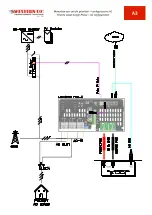
Page 87: ...d e prioritari configurazione DC WRM30 Standard and Priority Loads Single Phase Diagram DC configuration WRM30 A5 Schema monofase con carichi standard e prioritari configurazione DC WRM60 X SL Standard and Priority Loads Single Phase Diagram DC configuration WRM60 X SL A6 Schema parallelo con carichi standard e prioritari configurazione AC Standard and Priority Loads Parallel Diagram AC configurat...

Page 88: ......

Page 89: ......

Page 90: ......

Page 91: ......

Page 92: ......

Page 93: ......

Page 94: ...A7 ...

Page 95: ... Inverter 2 6 or higher WRM30 3 2 or higher WRM60 X 1 0 or higher 1 Se installato vedi schemi di installazione in Appendice A If installed see installation diagrams in Appendix A 2 Configurazione AC di fabbrica con batteria RESU LG Chem Standard AC configuration with RESU LG Chem battery 3 Tramite questa configurazione è possibile mantenere la batteria ad un livello SOC off costante in modo da far...

Page 96: ......

Page 97: ...oni contenute nel presente documento sono vietati senza il consenso scritto di WESTERN CO Srl This document is the property of WESTERN CO Srl All rights are reserved Reproduction and use of information contained within this document is forbidden without the written consent of WESTERN CO Srl Copyright 2018 Western CO Srl ...

Page 98: ......

Reviews: