background image

Lit. No. 94430/94431, Rev. 09 

24 

October 1, 2018

Vehicle           Wiring Harness

Spreader           Wiring Harness

CHMSL

White

Vehicle
Harness

White

Black

Orange

Black

Black

White

Black

Battery

Motor

+

_

Battery
Harness

Spreader
Harness

Fuse

Fuse holder

Butt
Connector

Red
Power Lead

Black

To

CHMSL

Vehicle
Stoplight
Harness

CHMSL
Extension
Cord

Speed

Control

White

Black

Red

Black

Speed

Control

Black

Red

White

Old Style

(no adapter required)

New Style

(adapter required)

12V DC (0.4kW motor)

Adapter

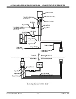
2-PIN HARNESS WIRING DIAGRAM – LOW-PROFILE SPREADERS

Summary of Contents for 1000

Page 1: ...This manual is for WESTERN Model 1000 2000 Low Profile Tailgate Spreaders with serial numbers 10003 and higher Model 1000 and 20364 and higher Model 2000 This manual supersedes all editions with an earlier date Low Profile Tailgate Spreader 68800 67440 Model 1000 2000 Owner s Manual Original Instructions ...

Page 2: ......

Page 3: ...Receiver Mount Spreader 10 Fixed Mount Spreader 11 SWING AWAY Spreader 12 OPERATING THE SPREADER 13 Driving and Spreading on Snow and Ice 13 Controls 14 Variable Speed PWM Control New Style 14 Variable Speed PWM Control Old Style 16 ON OFF Control 17 REMOVING THE SPREADER 18 Receiver Mount 18 Fixed Mount 18 SWING AWAY Mount 19 MAINTENANCE 20 Preseason Check 20 After Each Use 20 Postseason Maintena...

Page 4: ...___________________________ Weight ______________ lb kg Spreader Serial Number ______________________________________________________________________ PREFACE This manual has been prepared to acquaint you with the safety information operation and maintenance of your new spreader Please read this manual carefully and follow all recommendations This will help ensure profitable and trouble free operat...

Page 5: ...death or serious personal injury CAUTION Indicates a potentially hazardous situation that if not avoided may result in minor to moderate injury It may also be used to alert against unsafe practices Warning Caution Label both sides Warning Label receiver mount only Caution Label both sides SWING AWAY mount only WARNING CAUTION LABELS Please become familiar with and inform users about the warning an...

Page 6: ...AWR ratings as found on the driver side vehicle door cornerpost See Loading section to determine maximum volumes of spreading material CAUTION If rear directional CHMSL light or brake stoplights are obstructed by the spreader the lights shall be relocated or auxiliary directional or brake stoplights shall be installed WARNING Do not install the control for this product in the deployment path of an...

Page 7: ...g as the original Installing a fuse with a higher rating can damage the system and could start a fire Fuse Replacement including fuse ratings and locations is located in the Maintenance section of this Owner s Manual CAUTION During the hopper installation we recommend the addition of an OSHA compliant Backup Alarm This alarm is required for OSHA governed employers NOTE Lubricate grease fittings af...

Page 8: ...rade 8 Metric Fasteners Class 8 8 and 10 9 These torque values apply to fasteners except those noted in the instructions Torque ft lb Grade 5 Grade 8 Size Size Torque ft lb Class 8 8 Class 10 9 Torque ft lb Class 8 8 Class 10 9 Inch Fasteners Grade 5 and Grade 8 CAUTION Read instructions before assembling Fasteners should be finger tight until instructed to tighten according to torque chart Use st...

Page 9: ...ller to verify that struck load of snow or ice control material does not exceed GVWR or GAWR rating label and complies with FMVSS CAUTION Read and adhere to manufacturer s ice control material package labeling including Material Safety Data Sheet requirements 7 2 ft3 3 1 ft3 10 6 ft3 Model 2000 5 9 ft3 3 1 ft3 8 0 ft3 Model 1000 MATERIAL WEIGHTS Density Material lb ft3 lb yd3 kg m3 Salt 80 2160 12...

Page 10: ...parts CAUTION During removal or mounting securely grip spreader to avoid dropping 1 Attach the spreader to the receiver mount with six 3 8 x 1 cap screws 2 Insert the assembled unit into the receiver hitch and secure with pin not included 3 Plug the spreader harness into the vehicle harness 4 Use the supplied ratchet straps to secure the assembly to the vehicle frame Attaching the straps to the ve...

Page 11: ... flange of each top bracket to the bed rail using two 5 16 cap screws two 5 16 flat washers and two 5 16 locknuts per side NOTE Pay special attention when drilling or clamping dissimilar metals to aluminum bodies Galvanic corrosion can occur if not handled properly Contact vehicle manufacturer for recommended attachment practices 2 Place the spreader on the bumper and line up the holes in the bott...

Page 12: ...ling or clamping dissimilar metals to aluminum bodies Galvanic corrosion can occur if not handled properly Contact vehicle manufacturer for recommended attachment practices 2 Place the left and right base plates on the bumper of the truck and line up with the holes in the bumper 3 Attach the base plates to the bumper using three 3 8 cap screws three 3 8 plain washers any shims and three 3 8 locknu...

Page 13: ...You can have a serious or even fatal collision if you drive after drinking Please do not drink then drive or spread ice control materials OPERATING THE SPREADER Here are some tips for driving in these conditions Drive defensively Do not drink then drive or spread ice control materials Spread or drive only when you have good visibility for operating a vehicle If you cannot see well due to snow or i...

Page 14: ...s turned OFF while the spreader is running the motor will stop OPERATING THE SPREADER CONTROLS There are two control options They include the Variable Speed PWM Control and the ON OFF Control Both have had design changes Identify older and newer styles by the face plate diagrams below to find the appropriate operating instructions WARNING Before starting the spreader the driver shall verify all by...

Page 15: ... the speed dial NOTE When BLAST is used the speed dial does not move to the maximum speed setting but remains at the preset speed Diagnostic Indicator Light The diagnostic indicator light located to the right of the START BLAST button remains dark unless a problem with the motor or wiring is detected The light will flash a number of flashes in a row pause then repeat Count the flashes to determine...

Page 16: ...speed is needed 4 Release the power switch when maximum speed is no longer needed The switch automatically returns to the ON position and the speed shown on the speed dial NOTE When BLAST is used the speed dial does not move to the maximum speed setting but remains at the preset speed Spinner Indicator Lights Two lights on the cab control indicate the status of the motor Left light is red and indi...

Page 17: ...peed is needed When released the switch will automatically return to the OFF position and stop the motor If there are problems while operating the spreader refer to the Troubleshooting section in this manual NOTE Always place the cover on the hopper to prevent moisture buildup Do not let the spreader sit idle with material in the hopper for an extended period of time This can cause the material to...

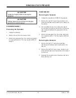
Page 18: ...cknuts that fasten the spreader to the bumper of the vehicle 3 Use an additional person or clamps to support the unit and then remove the four 3 8 cap screws and locknuts that fasten the spreader to the top brackets 4 Remove the spreader from the vehicle and stand in an upright position This may require additional support Removing the Brackets 1 Remove the two 1 2 cap screws washers and locknuts t...

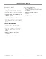
Page 19: ...port Removing the Top Brackets 1 Remove the two 1 2 cap screws washers and locknuts that fasten each top bracket to the bed rail 2 Remove the two 5 16 cap screws and locknuts that fasten each top bracket to the side of the bed rail 3 Mark the location of any shims to aid in reinstallation 4 Package the brackets with all hardware and store with the unit REMOVING THE SPREADER Removing the Base Plate...

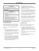
Page 20: ...tion of the motor cap assembly seal This seal is very important to the reliability of the unit Replace the seal if needed 7 Check the condition of the spinner disk If the vanes are excessively worn the unit may not spread as intended Replace the spinner if necessary 8 Replace the motor cap assembly and locknuts 9 Verify that vehicle stoplights and spreader CHMSL are visible and working properly AF...

Page 21: ...NCE POSTSEASON MAINTENANCE Before storing the unit for the off season taking a few minutes to do the following will extend the service life of your spreader 1 Thoroughly clean the unit inside and out 2 Apply dielectric grease to all electrical connections to prevent corrosion 3 Grease the drive shaft bearings 4 Oil or paint all bare metal surfaces 5 Place the lid on the hopper body of the unit and...

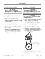
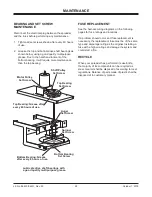
Page 22: ...ce of parts made of plastic shall be disposed of in customary manner BEARING AND SET SCREW MAINTENANCE Disconnect the electrical plug between the spreader and the truck before performing any maintenance 1 Tighten all set screws shown after every 60 hours of use 2 Grease the top and bottom drive shaft bearings as shown below using a good quality multipurpose grease Due to the harsh environment of t...

Page 23: ...tor 6A Fuse 14 ga Red To vehicle ignition accessory wire or fuse box 10 ga Red 30A Fuse 14 ga Black 8 ga Black 14 ga Orange To vehicle CHMSL signal Battery _ Vehicle Wiring Harness Spreader Wiring Harness Motor CHMSL Assembly 14 ga Orange 8 ga Black 14 ga Black A B Accessory Circuit 12A MAX 14 ga Yellow 8 ga Red 14 ga Yellow Accessory Circuit Motor Specification 12V DC 56 kW ...

Page 24: ...ck Battery Motor _ Battery Harness Spreader Harness Fuse Fuse holder Butt Connector Red Power Lead Black To CHMSL Vehicle Stoplight Harness CHMSL Extension Cord Speed Control White Black Red Black Speed Control Black Red White Old Style no adapter required New Style adapter required 12V DC 0 4kW motor Adapter 2 PIN HARNESS WIRING DIAGRAM LOW PROFILE SPREADERS ...

Page 25: ...eset the circuit breaker and turn the control ON Speed control dial on the Variable Speed PWM cab control does not change motor speed 1 Malfunctioning cab control 1 Replace cab control 2 Red and white connectors are incorrectly hooked up 2 Reconnect so that red matches red and white matches white Spreader does not operate Indicator light s illuminated 1 Overloaded condition is causing over current...

Page 26: ...ey set screw or replace pulley if damaged 4 Spinner pulley is not secured to spinner shaft 4 Replace cap screw and nut if missing or damaged Replace pulley if damaged 5 Spinner shaft bearings are dry or seized 5 Grease or replace bearings Ice control material not flowing Spinner is turning 1 Bridging of material or obstruction in hopper 1 Unplug the spreader harness and tag out if required Check h...

Page 27: ......

Page 28: ...ipment when so altered without reference to illustrations or specifications used Western Products or the vehicle manufacturer may require or recommend optional equipment for spreaders Do not exceed vehicle ratings with a spreader Western Products offers a limited warranty for all spreaders and accessories See separately printed page for this important information The following are registered trade...

Reviews: