


2-1
2. Unit Description
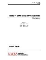
As shown in Figure 2.1, the NBB unit includes power outlets, LEDs and a
manual control button. The items shown in Figure 2.1 are described on the
following page.
PLUGS
READY
ACTIVITY
10BaseT
RS232
CONSOLE
(DTE)
PLUG 1
PLUG 2
PLUG 3
PLUG 14
PLUG 15
PLUG 16
PWR
CKT
A
PWR
CKT
B
Network
Boot Bar
www.wti.com
1
2
3
4
5
6
7
8
9
Figure 2.1: NBB-1600 Unit (120 VAC Model Shown)
Summary of Contents for NBB-1600-D20, NBB-1600DE-D20, NBB-1600CE-D16
Page 2: ......
Page 12: ...2 4 NBB 1600 D20 D16 Series Network Boot Bars User s Guide...
Page 18: ...3 6 NBB 1600 D20 D16 Series Network Boot Bars User s Guide...
Page 22: ...4 4 NBB 1600 D20 D16 Series Network Boot Bars User s Guide...
Page 57: ...Apx 1 A Interface Descriptions A 1 Console Port Interface Figure A 1 Console Port Interface...
Page 63: ......