


3.3. Hardware Overview
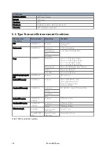
Figure 3. Location of interface ports and LEDs, illustrated by a Merlin-4407-T4-S2-LV model
No.
Description
No.
Description
1
WAN primary SMA connector
2
WAN auxiliary SMA connector
3
Reset button
4
Ethernet RJ45 ports
5
Power connection
6
Serial ports
7
USB-C Console port
8
Power and configuration LEDs
9
SIM LEDs
10
WAN signal strength
11
GPS SMA connector
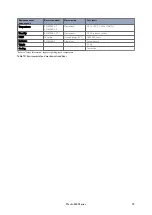
3.4. Connector Information Merlin
3.4.1. Power Input
Illustration
Position
Product marking
Direction
Description
1
DC+
Input
Supply voltage
2
DC-
Input
Supply voltage
Table 3. Power input
The positive input is marked with a plus sign, "+". The negative input is marked with a minus sign, "-". Connect
the voltage to the + pin and the return to the - pin on the power input.
NOTICE - POWER SUPPLY
Where an AC/DC-adapter has not been supplied, a power supply of no greater than 100 W
should be used, with a current limit of 1 Amp.
10
Merlin 4400 Series


