10
Installazione della caldaia
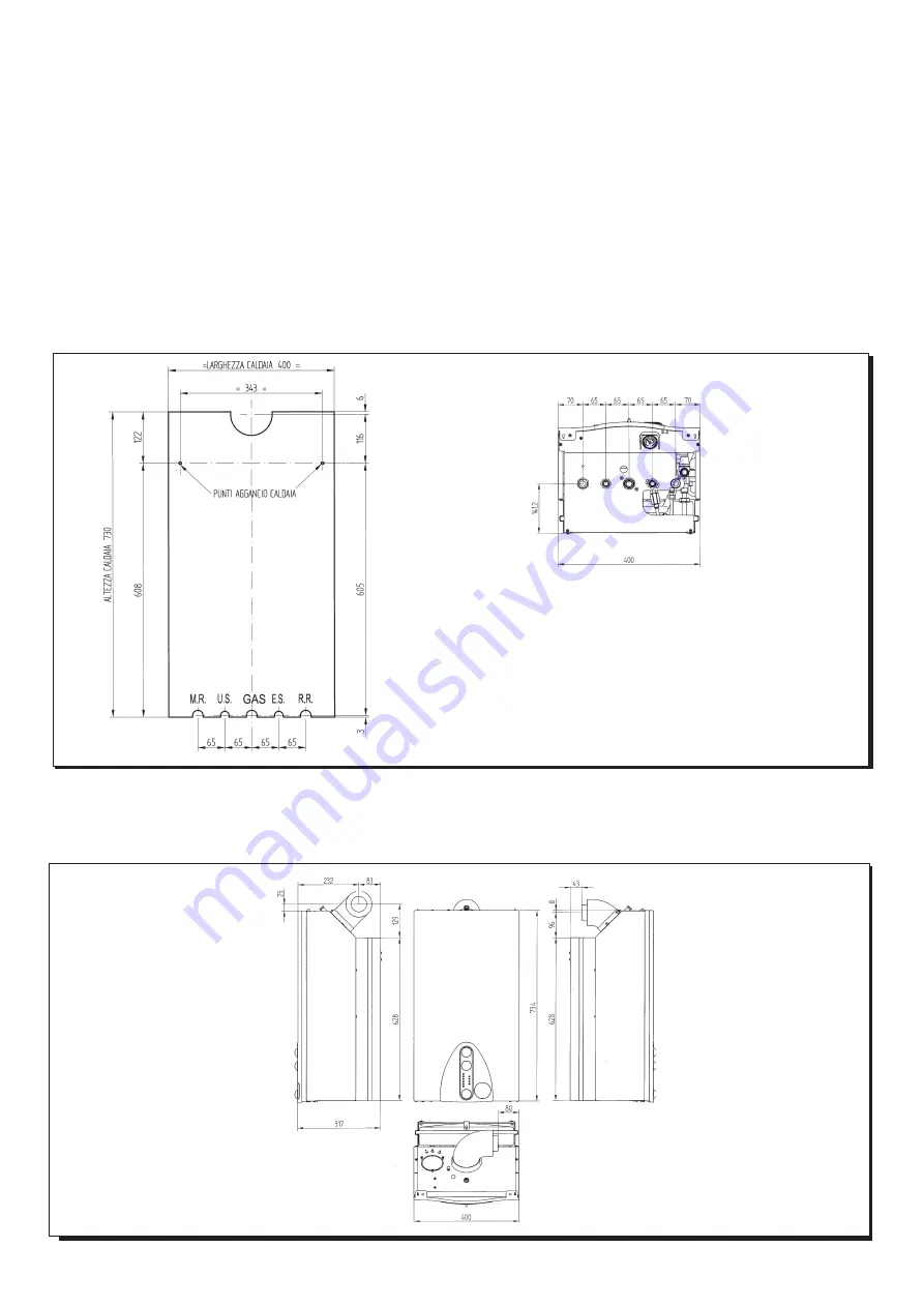
Determinata l’esatta ubicazione della caldaia fissare la dima alla parete.
Eseguire la posa in opera dell’impianto partendo dalla posizione degli
attacchi idrici e gas presenti nella traversa inferiore della dima stessa.
E’ consigliabile installare, sul circuito di riscaldamento, due rubinetti
d’intercettazione (mandata e ritorno) G3/4, disponibili a richiesta, che
permettono, in caso d’interventi importanti, di operare senza dover svuo-
tare tutto l’impianto di riscaldamento.
Nel caso di impianti già esistenti e nel caso di sostituzioni è consigliabile,
oltre a quanto citato, prevedere sul ritorno alla caldaia ed in basso un vaso
di decantazione destinato a raccogliere i depositi o scorie presenti anche
dopo il lavaggio e che nel tempo possono essere messi in circolazione.
Fissata la caldaia alla parete effettuare il collegamento ai condotti di
scarico e aspirazione, forniti come accessori, come descritto nei succes-
sivi capitoli.
The template to fix the boiler
on the wall
Decide upon the boiler location, then tape the template on the wall.
Connect the pipework to the gas and water inlets prearranged on the
template lower bar.
We suggest you fit two G3/4 stop cocks (available on demand) on the
central heating system flow and return pipework; the cocks will allow to
carry out important operations on the system without draining it
completely.
If you are either installing the boiler on a pre-existent system or
substituting it, we suggest you also fit settling tanks on the system return
pipework and under the boiler to collect the deposits and scaling which
may remain and be circulated in the system after the purge.
When the boiler is fixed on the template connect the flue and air ducts
(fittings supplied by the manufacturer) according to the instructions given
in the following sections.
Figura 5
MR: mandata riscaldamento G 3/4
US: uscita acqua calda sanitaria G 1/2
GAS: entrata gas alla caldaia G 3/4
ES: entrata acqua fredda sanitaria G 1/2
RR: ritorno impianto di riscaldamento G 3/4
MR: G3/4 heating flow
US: G1/2 domestic hot water outlet
GAS: G3/4 gas inlet to the boiler
ES: G1/2 cold water inlet
RR: G3/4 heating return
Figura 6
020130_0300
020130_0400
020221_1400
Boiler size
Dimensioni caldaia


