Page 17 of 24
PAM-190-P-A/I
5.3 Input signal adaptation
5.3.1
AIN (Analogue input scaling)
Command
Parameters
Unit
Group
AIN:W
A
B
C
X
a= -10000… 10000
b= -10000… 10000
c= -10000… 10000
x= V|C
-
-
0,01 %
-
STD
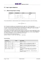
This command offers an individual scalable input. The following linear equation is used for the scaling.
)
(
c
Input
b
a
Output
The
“C” value
is the offset (e.g. to compensate the 4 mA in case of a 4… 20 mA input signal).
The variables
A
and
B
are defining the gain factor with which the signal range is scaled up to 100 % (e.g. 1.25
if using 4… 20mA input signal, defined in default current settings by A = 1250 and B = 1000). The internal
shunt for the current measuring is activated with switching the
X
value.
The gain factor is calculated by setting the usable range (
A
) in relation to the real used range (
B
) of the input
signal.
Usable are 0… 20mA, means (
A
) has the value
20
. Really used are 4… 20mA, means (
B
) has a value
of
16
(20-
4). Not used are 0… 4mA. In a range of 20mA this is an offset of 20%, means a value of
2000
for
(
C
). Last but not least (
X
) has to be set to
C
choosing current signal.
In this case AIN command would look like this:
AIN:I 20 16 2000 C or AIN:I 1250 1000 2000 C (see below)
Typical settings:
Command
Input
Description
AIN:X 1000 1000 0 V
0… 10 V
Range: 0… 100 %
AIN:X 10 8 1000 V
OR
AIN:X 1250 1000 1000 V
1… 9 V
Range: 0… 100 %; 1 V = 1000 used for the offset and
gained by 10 / 8 (10 V divided by 8 V (9 V -1 V))
AIN:X 10 4 500 V
OR
AIN:X 2500 1000 500 V
OR
0,5… 4,5 V
Range: 0… 100 %; 0,5 V = 500 used for the offset and
gained by 10 / 4 (10 V divided by 4 V (4,5 V -0,5 V))
AIN:X 20 16 2000 C
OR
AIN:X 2000 1600 2000 C
OR
AIN:X 1250 1000 2000 C
4… 20mA
Range: 0… 100 %
The offset will be compensated on 20 % (4 mA) and the
signal (16 mA = 20 mA
– 4 mA) will be gained to 100 %
(20 mA).
Each of this parameterization for 4… 20 mA is setting the
range to 0… 100 %.


