background image

9

48

2

53

12

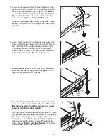
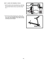
12. With the help of a second person, carefully raise the

Left Upright (53) and Right Upright (not shown), to a
vertical position. Attach the Storage Latch (48) to the
Left Upright (53) with two 3/4” Screws (2).

13.

Make sure that all parts used in assembly are properly tightened before you use the treadmill.

Keep

the included allen wrench in a secure place; the allen wrench is used to adjust the walking belt (see page
17). To protect the floor or carpet, place a mat under the treadmill. 

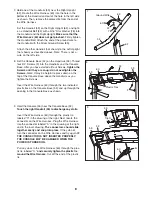
11. Lower the Uprights (53, 62) until the Handrails (59) are

touching the floor. 

See the lower drawing. Position the Uprights (53, 62) so
the treadmill Frame (79) is centered between them. 

Firmly tighten the four Upright Bolts (65) and the two
Frame Bolts (70). 

Be careful not to overtighten the

Frame Bolts. 

53

53, 62

59

70

79

62

Top View

11

65

52

No

Screw

60

2

59

2

2

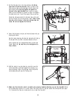
10. Set the Console (55) in the Console Base (52). 

Make

sure that no wires are pinched

. Insert as much of the

Wire Harness (60) as possible down into the hole in the
right Handrail (59). 

Securely tighten the plastic tie

nearest to the right Handrail.

Next, pull any excess

Wire Harness between the plastic ties tight, and tighten
the other plastic tie. Cut off the ends of the plastic ties. 

Attach the Console (65) to the Console Base (52) with
five 3/4” Screws (2) in the locations shown. 

Note: There

should not be a Screw in the hole indicated by the
arrow. Do not overtighten the Screws. 

55

Ties

10

Summary of Contents for CADENCE C44

Page 1: ...reference USER S MANUAL Serial Number Decal Visit our website at www weslo com new products prizes fitness tips and much more QUESTIONS As a manufacturer we are com mitted to providing complete customer satisfaction If you have questions or if parts are damaged or missing PLEASE CONTACT OUR CUSTOMER SERVICE DEPARTMENT DIRECTLY CALL TOLL FREE 1 866 699 3756 Mon Fri 6 a m 6 p m MST ON THE WEB www we...

Page 2: ...D AND MOVE THE TREADMILL 14 MAINTENANCE AND TROUBLESHOOTING 16 CONDITIONING GUIDELINES 18 ORDERING REPLACEMENT PARTS Back Cover LIMITED WARRANTY Back Cover Note A PART IDENTIFICATION CHART an EXPLODED DRAWING and a PART LIST are attached in the center of this manual WESLO is a registered trademark of ICON IP Inc ...

Page 3: ...see your local electronics store 12 Failure to use a properly functioning surge suppressor could result in damage to the con trol system of the treadmill If the control sys tem is damaged the walking belt may change speed accelerate or stop unexpectedly which may result in a fall and serious injury 13 Keep the power cord and the surge suppres sor away from heated surfaces 14 Never move the walking...

Page 4: ...ial rental or institutional setting WARNING Before beginning this or any exercise program consult your physician This is especially important for persons over the age of 35 or persons with pre existing health prob lems Read all instructions before using ICON assumes no responsibility for personal injury or prop erty damage sustained by or through the use of this product SAVE THESE INSTRUCTIONS The...

Page 5: ... manual To help us assist you note the product model number and serial number before calling The model number of the treadmill is WLTL29305 0 The serial number can be found on a decal attached to the treadmill see the front cover of this manual for the location To avoid a registration fee for any service needed under warranty you must register the treadmill at www wesloservice com registration Bef...

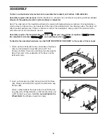
Page 6: ...rasive cleaner Assembly requires the included allen wrenches and your own phillips screwdriver two adjustable wrenches and needlenose pliers To identify the assembly hardware see the PART IDENTIFICATION CHART in the center of this manual 63 46 1 56 3 3 3 63 63 63 3 1 Attach six Base Pads 63 to the undersides of the Base 46 and the Extension Legs 56 with six 3 4 Tek Screws 3 Note There are small ho...

Page 7: ...Right Upright With the help of a second person lift and hold the Frame 79 between the Right Upright 62 and the Left Upright not shown Finger tighten a Frame Bolt 70 with a Washer 66 and a 3 8 Star Washer 29 through the Right Upright and the Frame Spacer 27 and into the Frame Do not tighten the Frame Bolt yet Repeat this step on the left side of the treadmill 46 29 62 79 27 66 70 3 Have a second pe...

Page 8: ...ily and snap into place If they do not turn the connector on the Wire Harness and try again IF THE CONNECTOR IS NOT INSERTED PROPERLY THE CONSOLE MAY BE DAMAGED WHEN THE POWER IS TURNED ON Pull any slack in the Wire Harness 60 through the plas tic tie labeled C and securely tighten the plastic tie around the Wire Harness Cut off the end of the plastic tie 59 52 55 A 60 Tie C 60 A 9 7 Hold one of t...

Page 9: ...3 62 so the treadmill Frame 79 is centered between them Firmly tighten the four Upright Bolts 65 and the two Frame Bolts 70 Be careful not to overtighten the Frame Bolts 53 53 62 59 70 79 62 Top View 11 65 52 No Screw 60 2 59 2 2 10 Set the Console 55 in the Console Base 52 Make sure that no wires are pinched Insert as much of the Wire Harness 60 as possible down into the hole in the right Handrai...

Page 10: ... mal function or break down grounding provides a path of least resistance for electric current to reduce the risk of electric shock This product is equipped with a cord having an equipment grounding conductor and a grounding plug Plug the power cord into a surge suppressor and plug the surge suppressor into an appropriate outlet that is properly installed and grounded in accordance with all local ...

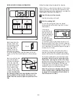
Page 11: ...e See the instructions at the left Start the walking belt To start the walking belt press the Speed increase button or the Walk Jog Run or Cool Down button If the Speed increase button is pressed the walk ing belt will begin to move at 1 mph As you exercise change the speed of the walking belt as desired by pressing the Speed increase and decrease buttons Each time a button is pressed the speed se...

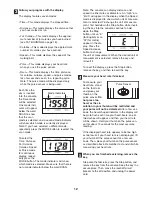
Page 12: ...ppear in the display when the Speed mode is displayed to show which unit of measure ment is selected To change the unit of measure ment first hold down the Stop button while insert ing the key into the console continue to hold down the Stop button until an E for English or an M for metric appear in the dis play Press the Speed increase button to change the unit of measurement When the desired unit...

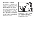
Page 13: ... shown at the right Next adjust the incline leg to the desired height and fully reinsert the incline pin Make sure that the incline pin is in the locked position shown in the inset drawing Adjust the other incline leg in the same way Make sure that both incline pins are inserted from the direction shown in the drawing CAUTION Before using the treadmill make sure that both incline legs are at the s...

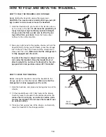
Page 14: ...atch Make sure that the storage latch is fully engaged over the catch To protect the floor or carpet from damage place a mat under the treadmill Keep the treadmill out of direct sunlight Do not leave the treadmill in the stor age position in temperatures above 85 Fahrenheit HOW TO MOVE THE TREADMILL Before moving the treadmill convert the treadmill to the storage position as described above Make s...

Page 15: ... latch to the left Pivot the frame down until the frame and the foot rail are past the storage latch 2 Hold the frame firmly with both hands and lower the frame to the floor Do not drop the frame to the floor To decrease the possibility of injury bend your legs and keep your back straight Closed Catch Storage Latch ...

Page 16: ... back in PROBLEM The power turns off during use SOLUTION a Check the reset off circuit breaker located on the treadmill frame near the power cord see 1 c above If the circuit breaker has tripped wait for five minutes and then press the switch back in b Make sure that the power cord is plugged in If the power cord is plugged in unplug it wait for five minutes and then plug it back in c Remove the k...

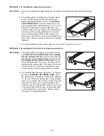
Page 17: ...enter or slips when walked on SOLUTION a If the walking belt is off center first remove the key and UNPLUG THE POWER CORD If the walking belt has shifted to the left use the allen wrench to turn the left rear roller bolt clockwise 1 2 of a turn if the walking belt has shifted to the right turn the bolt counterclockwise 1 2 of a turn Be careful not to overtighten the walking belt Then plug in the p...

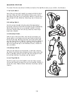
Page 18: ...s activity that requires large amounts of oxygen for prolonged periods of time This increases the demand on the heart to pump blood to the muscles and on the lungs to oxygenate the blood For aerobic exercise adjust the speed and incline of the treadmill until your heart rate is near the highest number in your training zone WORKOUT GUIDELINES Each workout should include the following three parts A ...

Page 19: ...lles Stretch With one leg in front of the other reach forward and place your hands against a wall Keep your back leg straight and your back foot flat on the floor Bend your front leg lean forward and move your hips toward the wall Hold for 15 counts then relax Repeat 3 times for each leg To cause further stretching of the achilles ten dons bend your back leg as well Stretches Calves achilles ten d...

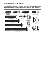
Page 20: ... 29 2 3 4 Screw 2 13 3 4 Tek Screw 3 6 Handrail Bolt 42 2 Extension Leg Screw 89 4 Frame Bolt 70 2 5 16 Star Washer 78 2 Spacer Screw 45 2 Remove this chart and use it to identify small parts during assembly Save this chart and the EXPLODED DRAWING PART LIST for future reference PART IDENTIFICATION CHART ...

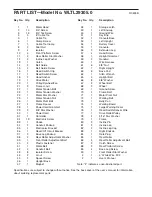
Page 21: ...ew 44 2 U nut 45 2 Spacer Screw 46 1 Upright Base 47 1 Magnet 48 1 Storage Latch 49 1 Left Endcap 50 1 Ground Wire 51 1 Key Clip 52 1 Console Base 53 1 Left Upright 54 1 Battery Cover 55 1 Console 56 2 Extension Leg 57 4 Hood Screw 58 1 Upright Grommet 59 2 Handrail 60 1 Wire Harness 61 6 3 8 Nut 62 1 Right Upright 63 6 Base Pad 64 1 Allen Wrench 65 4 Upright Bolt 66 8 3 8 Washer 67 2 Wheel Bolt 6...

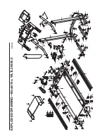
Page 22: ... 81 85 49 38 86 64 88 87 13 80 14 15 8 1 32 50 3 3 12 12 41 40 40 67 68 61 63 3 63 3 63 3 70 48 2 2 2 2 2 2 52 54 62 53 59 59 46 58 60 61 9 43 9 43 37 60 55 70 29 29 66 66 65 65 65 66 65 66 9 43 10 9 43 10 32 42 44 44 34 42 2 56 89 89 31 35 32 32 32 33 34 66 63 3 61 68 67 37 56 66 78 78 63 3 63 3 69 66 66 75 84 90 11 11 EXPLODED DRAWING Model No WLTL29305 0 R0805B ...

Page 23: ...customer will be responsible for a minimal trip charge This warranty does not extend to any product or damage to a product caused by or attributable to freight damage abuse misuse improper or abnormal usage or repairs not provided by an ICON authorized service center to products used for commercial or rental purposes or to products used as store display models No other warranty beyond that specifi...

Reviews: