Weslo CADENCE 26.0 User Manual Download Page 21

21


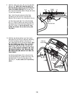
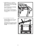
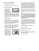
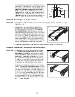
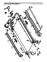
   Locate the Reed Switch (46) and the Magnet (44) on 

the left side of the Pulley (43). Turn the Pulley until the 

Magnet is aligned with the Reed Switch. Make sure 

that the gap between the Magnet and the Reed 

Switch is about 1/8 in. (3 mm). If necessary, loosen 

the #8 x 3/4” Tek Screw (20), move the Reed Switch 

slightly, and then retighten the Tek Screw. Reattach 

the Motor Hood (not shown), and run the treadmill for 

a few minutes to check for a correct speed reading. 

PROBLEM:  The walking belt slows when walked on

SOLUTION: a.       If an extension cord is needed, use only a 3-conductor, 14-gauge (1 mm

2

) cord that is no longer 

than 5 ft. (1.5 m).  


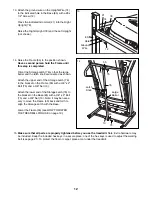
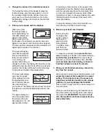
b.   If the walking belt is overtightened, treadmill per-

formance may decrease and the walking belt may 

become damaged. Remove the key and UNPLUG 

THE POWER CORD. Using the hex key, turn both 

idler roller bolts counterclockwise, 1/4 of a turn. When 

the walking belt is properly tightened, you should be 

able to lift each edge of the walking belt 2 to 3 in. (5 to 

7 cm) off the walking platform. Be careful to keep the 

walking belt centered. Then, plug in the power cord, 

insert the key, and run the treadmill for a few minutes. 

Repeat until the walking belt is properly tightened.


c.  If the walking belt still slows when walked on, please see the front cover of this manual.

PROBLEM:  The walking belt is off-center or slips when walked on

SOLUTION: a.   If the walking belt is off-center, first remove the key 

and UNPLUG THE POWER CORD. If the walking 

belt has shifted to the left, use the hex key to turn 

the left idler roller bolt clockwise 1/2 of a turn; if the 

walking belt has shifted to the right, turn the left 

bolt counterclockwise 1/2 of a turn. Be careful not to 

overtighten the walking belt. Then, plug in the power 

cord, insert the key, and run the treadmill for a few 

minutes. Repeat until the walking belt is centered. 


b.   If the walking belt slips when walked on, first remove 

the key and UNPLUG THE POWER CORD. Using the 

hex key, turn both idler roller bolts clockwise, 1/4 of a 

turn. When the walking belt is correctly tightened, you 

should be able to lift each edge of the walking belt 2 

to 3 in. (5 to 7 cm) off the walking platform. Be careful 

to keep the walking belt centered. Then, plug in the 

power cord, insert the key, and carefully walk on the 

treadmill for a few minutes. Repeat until the walking 

belt is properly tightened.


Idler Roller Bolts

2–3 in.

b

a

b

44

46

20

Top 

View

43

1/8 in.

Summary of Contents for CADENCE 26.0

Page 1: ...future reference www iconeurope com Serial Number Decal CUSTOMER CARE UNITED KINGDOM Call 08457 089 009 From Ireland 053 92 36102 Website www iconsupport eu E mail csuk iconeurope com Write ICON Heal...

Page 2: ...ING REPLACEMENT PARTS Back Cover RECYCLING INFORMATION Back Cover This drawing shows the locations of the warning decals If a decal is missing or illegible call the telephone number on the front cover...

Page 3: ...the power cord see page 13 plug the power cord into an earthed circuit No other appliance should be on the same circuit When replacing the fuse in the power cord adapter insert an ASTA approved BS1362...

Page 4: ...ct and properly tighten all parts of the treadmill regularly 23 Never insert any object into any opening on the treadmill 24 DANGER Always unplug the power cord immediately after use before clean ing...

Page 5: ...he treadmill If you have questions after reading this manual please see the front cover of this manual To help us assist you note the product model number and serial number before contacting us The mo...

Page 6: ...llips screwdriver rubber mallet adjustable wrench wire cutters and needlenose pliers Use the drawings below to identify the assembly hardware The number in parentheses below each drawing is the key nu...

Page 7: ...8 and two 3 8 Star Washers 9 do not tighten the Bolts yet Orient the Left Upright 77 as shown and attach it to the Base 85 with two 3 8 x 2 1 4 Bolts 8 and two 3 8 Star Washers 9 do not tighten the Bo...

Page 8: ...e Lift Frame with a 3 8 x 2 1 2 Bolt 1 a 3 8 Washer 10 and a 3 8 Nut 13 do not tighten the Bolt yet 4 78 1 1 79 79 10 13 13 65 10 65 78 79 Grease Outer Side 5 See the left inset drawing Identify the o...

Page 9: ...ert the brackets on the console assembly into the Right Upright and the Left Upright 77 Be careful not to pinch any wires Attach the console assembly with four 5 16 x 3 4 Bolts 2 and four 5 16 Star Wa...

Page 10: ...careful not to pinch any wires 10 Hold the handrail assembly near the console assembly Connect the wire harness extending from the handrail assembly to the wire har ness extending from the console ass...

Page 11: ...e lower ends of the Handrails 69 71 against the Uprights 77 78 as you tighten the four 1 4 x 1 2 Bolts 6 Then tighten the 1 4 x 1 1 2 Bolts 3 12 Lower the Uprights 77 78 as shown See the inset drawing...

Page 12: ...e floor or carpet place a mat under the treadmill 14 Raise the Frame 55 to the position shown Have a second person hold the Frame until this step is completed Orient the Storage Latch 76 so that the l...

Page 13: ...ing in the power cord in Australia go to step 3 If you are plugging in the power cord in the UK first press the pins on the power cord into the metal clips in the adapter as shown Close the adapter co...

Page 14: ...es you through an effective exercise session To turn on the power see page 15 To use the man ual mode see page 15 To use a preset workout see page 17 To use the information mode see page 18 IMPORTANT...

Page 15: ...lt to slow to a stop Test the clip by carefully taking a few steps backward if the key is not pulled from the console adjust the position of the clip HOW TO USE THE MANUAL MODE 1 Insert the key into t...

Page 16: ...hat you have walked or run the approximate number of calories you have burned or the speed of the walking belt Press the Display button repeatedly until the upper display shows the information that yo...

Page 17: ...for the current segment At the end of each segment a series of tones will sound and the next segment of the profile will begin to flash If a different speed and or incline setting is programmed for t...

Page 18: ...belt has moved An M for metric kilometers or an E for English miles will appear in the lower right display Press the Speed increase button to change the unit of measurement if desired The console fea...

Page 19: ...atch knob is locked in the storage position Moving the treadmill may require two persons 1 Hold the frame and one of the handrails and place one foot against a wheel 2 Pull back on the handrail until...

Page 20: ...g it back in c Remove the key from the console Reinsert the key into the console d If the treadmill still will not run see the front cover of this manual PROBLEM The console displays remain lit when y...

Page 21: ...d run the treadmill for a few minutes Repeat until the walking belt is properly tightened c If the walking belt still slows when walked on please see the front cover of this manual PROBLEM The walking...

Page 22: ...your goal is to strengthen your cardiovascular system you must perform aerobic ex ercise which is activity that requires large amounts of oxygen for prolonged periods of time For aerobic exercise adju...

Page 23: ...41 2 Belt Guide 42 2 Frame Pivot Spacer 43 1 Drive Roller Pulley 44 1 Magnet 45 1 Reed Switch Clamp 46 1 Reed Switch 47 1 Drive Motor 48 1 Motor Belt 49 1 Walking Belt 50 1 Power Cord 51 1 Power Cord...

Page 24: ...4 57 20 59 60 12 61 20 34 55 37 41 40 45 42 15 34 34 44 39 38 38 58 12 22 22 47 28 17 48 17 28 42 56 14 27 27 27 27 27 27 27 33 20 20 18 40 31 31 20 20 50 96 51 12 30 53 52 12 30 76 13 75 13 75 98 97...

Page 25: ...25 24 62 23 29 13 65 26 25 63 13 33 33 64 23 29 68 12 67 20 20 20 66 12 101 100 30 12 12 12 102 16 20 99 EXPLODED DRAWING B Model No WETL59710 0 R1013A...

Page 26: ...77 80 79 81 20 10 1 80 79 1 10 85 9 8 81 20 84 8 83 83 13 13 83 84 83 8 82 82 69 71 70 72 6 11 6 11 2 2 5 5 2 5 2 7 9 8 7 7 7 3 4 3 4 5 73 74 86 12 21 21 81 20 81 20 EXPLODED DRAWING C Model No WETL59...

Page 27: ...27 87 35 35 35 35 35 35 35 35 35 89 7 35 94 93 95 35 35 35 7 7 7 7 35 35 91 91 92 35 35 90 3 88 7 32 31 11 EXPLODED DRAWING D Model No WETL59710 0 R1013A...

Page 28: ...d the EXPLODED DRAWING near the end of this manual This electronic product must not be disposed of in municipal waste To pre serve the environment this product must be recycled after its useful life a...

Reviews: