Wenglor SS2-00VA000R3 Operating Instructions Manual Download Page 8

8

EN

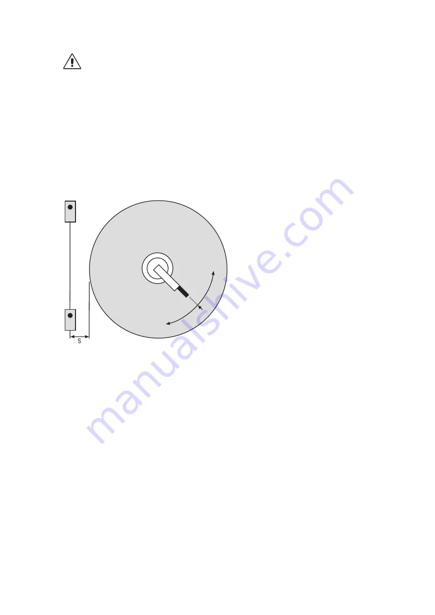
2.2 Securing the Danger Zone


The danger zone must be secured by means of the light barriers alone, or by means of the light barriers in  
combination with additional mechanical safety devices. Reaching around, over and/or under the safety field must 
be prevented in any case. It must be impossible to approach the point of danger without passing through the light 
barriers. The safety field is located between the beam emission of the sender and the beam entry at the receiver. The 
beam diameter is smaller than 30 mm.

The Light Barriers are only allowed to be used to secure access according to EN ISO 13855. The use for  
finger and hand protection is not allowed.

2.3 Safety Clearance per EN ISO 13855

Safety clearance S is calculated with the following formula in accordance with EN ISO 13855: S = K × T +C
A gripping speed of 1,6 meters per second is assumed.
Example:

Danger Zone

Standstill

Standstill

Stop Signal

S =   Minimum safety clearance in mm, measured from the danger zone to the point of detection, to the line of 

detection or to the safety field.

K =  Approach speed constant in mm per sec. = 1600 mm per sec.
T =  Total response time (t1 + t2) in seconds
t1 =  Response time of the Individual Light Barrier Control Unit in seconds
t2 =  Machine or process over-travel time in seconds
C =   Additional clearance in mm (margin), which is based upon penetration into the danger zone before the safety 

device is triggered

Obstruction of the safety field during hazardous motion results in immediate shutdown. The distance between  
the safety field and the point of danger must be large enough to assure that the point of danger cannot be  
reached until hazardous motion has come to a standstill. This safety clearance depends upon total over-travel time, 
as well as the person’s maximum gripping or walking speed.

Total over-travel time is the sum of maximum response time of the ESPE and maximum over-travel time of the  
hazardous motion. Machine over-travel time must be determined by means of repeated measurement prior to  
initial start-up, and each time the machine is retooled or set up.

In order to secure the danger zones, the safety heights set forth in EN ISO 13855 are determined by means of a risk 
analysis in accordance with EN ISO 13849-1.

Summary of Contents for SS2-00VA000R3

Page 1: ...SS2 00VA000R3 Individual Safety Light Barrier Control Unit Operating instructions Available as PDF only Status 02 05 2016 www wenglor com EN...

Page 2: ...2 Parallel Approach to the Safety Field 10 2 4 Minimum Clearance to Reflective Surfaces 10 2 5 Mutual interference of the Light Barriers 11 3 Connection and Installation to the Machine 11 3 1 General...

Page 3: ...ride 26 7 1 Basics 26 7 2 Settings 26 7 2 1 Selecting the Mode of Operation 26 7 2 2 Override with Continuous Command 27 7 2 3 Override with Command Pulse 27 8 Functions and Operation 28 8 1 Use of On...

Page 4: ...14 Technical Data 32 14 1 Safety Light Barriers 32 14 2 Individual Light Barrier Control Unit 33 15 Checklist 35 16 Certification 35 17 EC Declaration of Conformity 36 17 1 Declaration of conformity...

Page 5: ...us motion can be stopped electrically by the safety output of the Individual Light Barrier Control Unit The use of a type 2 safety device is permissible in accordance with the risk analysis After comp...

Page 6: ...bots 1 3 2 Multiple Barrier Protection Use for access monitoring 1 3 3 Muting Function Safety Light Barrier Receiver Muting Sensor Receiver 1 Muting Sensor Receiver 2 Safety Light Barrier Transmitter...

Page 7: ...types 1 5 Explanation of Utilized Symbols Makes reference to a measure for the prevention of a concrete danger Illustrates suggestions and instructions which make use of the controller easier 2 Import...

Page 8: ...ion to the line of detection or to the safety field K Approach speed constant in mm per sec 1600 mm per sec T Total response time t1 t2 in seconds t1 Response time of the Individual Light Barrier Cont...

Page 9: ...t1 t2 C 1200 mm Direction of Approach If more than one light barrier is used the table included below applies C Margin for penetration into the dan ger zone before the safety device is tripped never...

Page 10: ...0 4 H K 1600 mm per second S K t1 t2 C 1200 mm 0 4 H Direction of Approach S Minimum safety clearance H Height of the safety field 2 4 Minimum Clearance to Reflective Surfaces If reflective surfaces...

Page 11: ...eceiver Emitter Receiver 3 Connection and Installation to the Machine 3 1 General The Individual Light Barrier Control Unit must be integrated into the system such that at least IP 54 protection is as...

Page 12: ...ical motors inverters frequency variators as well as any other sources of interference The connector cables between the control unit and the sensors connector cables to the test command generator and...

Page 13: ...d Off Channel 2 unobstructed or unused OSSD DIAG Green Red Yellow Red Output relay open Red blinking The number of pulses indicates the type of failure only when CH2 Failure is on Green Output replay...

Page 14: ...p 23 section 6 2 3 24 V DC 4 Muting duration 1 I p 24 section 6 3 5 Muting duration 2 I p 24 section 6 3 6 Restart inhibit I p 19 section 4 2 3 7 Override 1 I p 26 section 7 8 Override 2 I p 26 secti...

Page 15: ...input 1 I p 23 section 6 2 13 0 V 2 Muting input 2 I p 23 section 6 2 14 PE ground 3 24 V DC 15 Acknowledgement input I p 18 section 4 2 4 Muting duration 1 I p 24 section 6 3 16 Test input I p 18 sec...

Page 16: ...ther Information 1 Muting input 1 I p 23 section 6 2 13 0 V 2 Muting input 2 I p 23 section 6 2 14 PE ground 3 24 V DC 15 Acknowledgement input I p 18 section 4 2 4 Muting duration 1 I p 24 section 6...

Page 17: ...tion Input Output Further Information 1 Muting input 1 I p 23 section 6 2 13 0 V 2 Muting input 2 I p 23 section 6 2 14 PE ground 3 24 V DC 15 Acknowledgement input I p 18 section 4 2 4 Muting duratio...

Page 18: ...can be setup with either restart inhibit of automatic restart The use of restart inhibit start and restart disabled is required if the safety device is used to secure a passageway to the danger zone a...

Page 19: ...s acknowledgement input terminal 15 from a pushbutton or by means of an appropriate command for example from a PLC After penetration into the protected area the relay outputs are deactivated and can o...

Page 20: ...tactor monitoring is used to determine whether or not external contactors or auxiliary contact elements func tion properly External contactors may only be connected if they are equipped with positivel...

Page 21: ...Terminal Designation Input Output Further Information 1 Muting input 1 I p 23 section 6 2 13 0 V 2 Muting input 2 I p 23 section 6 2 14 PE ground 3 24 V DC 15 Acknowledgement input I p 18 section 4 2...

Page 22: ...muting signal output The muting sensors serve as a receiving system which decides whether the muting function will be activated or deactivated Monitoring of the dangerous passageway is only interrupte...

Page 23: ...must above all be adhered to when the material is uneven is shifted when it enters the muting zone or if its height changes 6 2 Connecting the Muting Sensors and the Muting Indicator 6 2 1 Muting Sens...

Page 24: ...muting sensors and the muting indicator Any wenglor light barrier with an antivalent PNP output the output must read out 24 V as long as the light beam is unobstructed can be used as a muting sensor...

Page 25: ...ing Sensor 2 Receiverr Muting Sensor 2 Receiver Muting Sensor 1 Transmitter Receiver Object which Triggers Muting After muting has been activated as a re sult of obstruction of both muting sen sors wi...

Page 26: ...e the safety light barrier and or at least one muting sensor is obstructed The override display blinks in this case see section 8 3 The override mode sets the OSSD outputs to ON and makes it possible...

Page 27: ...nd 8 or all safety light barriers and muting sensors are unobstructed or 15 minutes have elapsed since initial activation The last two points are reset after a complete muting sequence has been comple...

Page 28: ...ed green yellow On Red Red Start up test Off Off Red Channel obstructed outputs off Off Green Red On Off Red On Green Yellow Channel unobstructed outputs off unit is waiting for restart On Green Green...

Page 29: ...ting duration the muting indicator and override Off Red 6 pulses red Configuration changed without restart Switch the unit off an back on again to eliminate the problem Switch the unit off and back on...

Page 30: ...nel CH1 CH2 The check list for initial operation Chapter 13 helps executing the testing 10 2 Daily Inspection and Maintenance Regular inspections must be completed in accordance with local ordinances...

Page 31: ...accordance with all respectively valid national waste disposal regulations The housings of the individual Safety Light Barriers and the Individual Light Barrier Control Unit are made of plastic and c...

Page 32: ...t Barrier Control Unit Light Barriers and the re quired Connector Cables must be ordered Operating instructions are included in the scope of delivery The transmitter and the receiver used for a given...

Page 33: ...specified with this value After this point in time PFHd SIL and PL values can no longer be guaranteed and replacement of the relays becomes mandatory A T10d value of greater than 20 years means that t...

Page 34: ...put 40 ms Muting sensor inputs 2 pairs of sensors transmitter receiver 24 V DC PNP Muting enable input 24 V DC PNP Override time limit 60 min Operating modes restart inhibit or automatic restart LED d...

Page 35: ...ion Yes No Have additional mechanical protective measures been installed which prevent reaching under over or around the safety field and are they protected against manipulation Yes No 4 Installation...

Page 36: ...36 EN 17 EU Declaration of Conformity 17 1 Declaration of conformity for Individual Safety Light Barrier Control Units SS2...

Page 37: ...37 17 2 Declaration of conformity for Safety Through Beam Sensor SL2 w...

Reviews: