background image

21

9.  Network Settings

To operate the device in an Ethernet LAN, the device and the remote station, for example a computer, must be 
located in the same network. The IP-Address of the device is set to the IP-Address 192.168.100.1 and to the 
subnet mask 255.255.255.0 and standard gateway 192.168.100.254. In the instructions the default values are 
always assumed.

WARNING:  It must be ensured that supply power is not interrupted while making changes to network 

settings. Furthermore, supply power must maintained for at least an additional 5 minutes 
after the network settings have been saved to memory.

10.  Web-based configuration

The device is equipped with a web-based adjustment interface that works independent of the operating system.
You can configure the device conveniently using a standard web browser (e.g. Internet Explorer or Firefox).

10.1.  Invoking the Management Interface

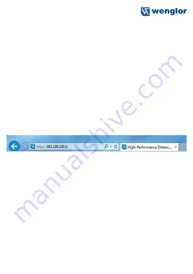
Start the web browser. Enter the IP-Address of the device in the address line of your browser, and press the 
Enter button. The IP-Address is preset to 192.168.100.1.

Example: http:\\192.168.100.1 

The overview page “Device general” is not password protected. If other pages are accessed, a password  
request appears. The following user data is preset in the default settings:

User name: admin
Password: admin

The password can be changed on the “Device settings” page.

Summary of Contents for OY2TA104P0150P

Page 1: ...EN OY2TA104P0150P High Performance Distance Sensor Operating Instructions Available as PDF only Status 24 08 2016 wenglor com ...

Page 2: ...g Instructions 8 6 Initial Operation 8 6 1 Initial Operation 8 6 2 Default Settings 9 7 Functional Overview OLED Display 10 7 1 Run 12 7 2 Display 12 7 2 1 Display Mode 12 7 2 2 Display Intensity 13 7 3 Filter 13 7 4 Output Rate 13 7 5 Laser 14 7 6 I O Test 14 7 7 Network 15 7 8 Language 15 7 9 Info 15 7 10 Reset 16 7 11 Password 16 8 Information on PROFINET 17 8 1 Overview of Device Access Point ...

Page 3: ...sed configuration 21 10 1 Invoking the Management Interface 21 10 2 Page layout 22 10 3 Device general 23 10 4 Device Settings 24 10 5 Measured Value Settings 25 10 6 Device Test 25 11 Maintenance Instructions 26 12 Proper Disposal 26 ...

Page 4: ...al sensors next to or across from each other without them influencing each other 2 Safety Precautions 2 1 Safety Precautions This operating instruction is part of the product and must be kept during its entire service life Read this operating instruction carefully before using the product Installation start up and maintenance of this product has only to be carried out by trained personal Tampering...

Page 5: ... Laser Class EN 60825 1 1 Beam Divergence 2 mrad Light Spot Diameter see table 1 Port Type 100BASE TX PoE Class 1 Response Time 10 ms Temperature Range 25 50 C Reverse Polarity Protection yes Protection Class III Adjustment Menu OLED Housing Plastic Degree of Protection IP68 Connection M12 1 8 pin Webserver yes Control Panel No X2 T10 PROFINET IO CC B Light Spot Diameter Working Distance 0 10 m Li...

Page 6: ...ctor Monitoring Encoder A A TTL Encoder B B TTL Black Brown Red Orange Yellow Green Blue Violet Grey White Pink Green Yellow Supply Voltage Supply Voltage 0 V Supply Voltage AC Voltage Switching Output NO Switching Output NC Contamination Error Output NO Contamination Error Output NC Input analog or digital Teach Input Time Delay activation Shielding Interface Receive Path Interface Send Path Read...

Page 7: ...84 Communication Status 85 Link Act LED Designation Condition Function CS Communication Status Off Connection AR with controller established Green Protocol not initialized Red No connection AR with controller established MS Modul Status Red Error class FATAL Red flashing Detection function may be activated via Engineering Tool L A Green Links present Green flashing Communication ...

Page 8: ...plications Caution In the case of operation on a control unit settings that were changed on the website or using the OLED display will be overwritten by the control unit If you want to start up the device on a control unit please perform the following steps Connect the Sensor to a switch with PoE using an appropriate cable M12 1 8 pin In the case of a switch without PoE please use the Midspan Adap...

Page 9: ...y Mode Process Intensity Screensaver Filter 1 Laser ON Network IP Address 192 168 100 1 Subnet Mask 255 255 255 0 DHCP DHCP OFF Std Gateway 192 168 100 254 MAC Address See type plate on the product Language English Password Activate Off Change 0 ...

Page 10: ...un Mode Enable Change Lock Language Info Reset Password Run Min Medium Max Power save Screensaver Process Text Analyse Network Mode Rotate Intensity Display Filter 1 10 100 2 20 5 50 Laser On Off E A Test Value in µm No of Status Bit OK Warmup OK Too low Too high Measured Value Status Bits Warmup Signal Temperature Run Mode Network IP address Subnet Mask Std Gateway ...

Page 11: ...ation menu by pressing any button Note If no setting is made in the configuration menu for a period of 30 s the Sensor returns automatically to the display view Pressing the button again returns the Sensor to the last menu view used If a setting is made it becomes active once you leave the configuration menu Important To prevent any damage to the buttons please do not use any pointed objects for s...

Page 12: ... by 180 The rotation is canceled by pressing this button again Intensity Set the display intensity see chapter 7 2 2 7 2 1 Display Mode The measured value in mm and the PROFINET device name always appear in the Sensor s display offline will be displayed here unless the PROFINET device name has been changed You can choose from the following additional displays in the menu item display mode Mode Adj...

Page 13: ...ed values over which the Sensor takes an average The larger the filter selected the slower the response time of the Sensor becomes when there is a change in the measured values A larger filter improves the reproducibility of the Sensor Filter Number of values for averaging 1 2 5 10 20 50 100 3 Back 7 Run If 1 is selected each measured value is output directly without averaging When ever a value gr...

Page 14: ...object too small The current measured value is below the working range Measuring range lower limit 3 Distance to object too large The current measured value is above the working range Measuring range upper limit 4 No signal The sensor does not detect an object within its working range Measuring range upper limit 5 Signal too weak Too little light is reflected back to the sen sor from the object e ...

Page 15: ...t MAC Address Net Reset Reset network settings to the default settings 7 7 Language The menu language can be changed in the menu item Language The user is automatically prompted for his desired language at initial operation and after each reset Language Set menu language Deutsch English Francais Espanol Italiano 3 Back 7 Run The menu appears in the selected language immediately after selection 7 8...

Page 16: ... operation of the Sensor is disabled after supply power has been interrupted and is only enabled after successfully entering password Change Change password Lock Locking Sensor causes an immediate disabling of operation if activate Password is set to on If the password functionality is activated the password must be entered before each operation of the Sensor After correctly entering the password ...

Page 17: ...e 0 not rotated 1 rotated Display Intensity BitArea 0 0 3 4 Screensaver 0 4 Yes 303 1 Byte 0 Min 1 Normal 2 Max 3 Power saver mode 4 Screensaver Display mode BitArea 0 0 3 0 Process 0 3 Yes 304 1 Byte 0 Process 1 Analysis 2 Text 3 Network Language BitArea 0 0 3 1 English 0 4 Yes 305 1 Byte 0 Deutsch 1 English 2 Français 3 Español 4 Italiano 8 2 Overview of modules used in the DAP OY2TA104P0150P Na...

Page 18: ...ta Type Index Presetting Changeable Filter 0 6 Unsigned8 257 0 yes Laser 0 1 Bit 264 0 yes Module Status Module ID 2 Submodule 1 Slot 2 Format Cyclical Data Input Output Value Range Data Type Unit Description Statusbits Bit Unsigned32 Bit0 General Bit1 Distance to Object is too small Bit2 Distance to Object is too large Bit3 No signal Bit4 Contamination Bit5 Signal too high Bit6 Warm up procedure ...

Page 19: ...ange Data Type Index Module Laser ON OFF Module ID 4 Submodule 1 Slot 4 Format Cyclical Data Input Output Value Range Data Type Unit Description Laser ON OFF Laser ON OFF 0 1 Unsigned8 0 Laser ON 1 Laser OFF Parameter Name Value Range Data Type Index Module Display Text Module ID 5 Submodule 1 Slot 5 Format Cyclical Data Input Output Value Range Data Type Unit Description Display Text Display Text...

Page 20: ...d 0x01 Learn offset value 0x03 Reset offset value 0x04 Apply offset 0x05 Reset offset Input Value Range Data Type Unit Description 0x00 0x10 Unsigned8 0x00 Ready for command 0x10 Command executed Parameter Name Wertebereich Datentyp Index Examples Learn offset value Input 0x00 0x01 Output 0x00 0x10 Apply offset value Input 0x00 0x04 Output 0x00 0x10 ...

Page 21: ...ettings have been saved to memory 10 Web based configuration The device is equipped with a web based adjustment interface that works independent of the operating system You can configure the device conveniently using a standard web browser e g Internet Explorer or Firefox 10 1 Invoking the Management Interface Start the web browser Enter the IP Address of the device in the address line of your bro...

Page 22: ...ike on the device itself 3 Category selection The web based settings are divided into four categories Device general Overview page with general information about the device Device settings Network and display settings of the device Measured value settings Settings for influencing the measured value of the device Device Test Manual change of the Sensor output in order to test the process 4 Page con...

Page 23: ... the overview page Device general is displayed Device Name A unique device name can be freely assigned to each device via the PROFINET control The device name is also displayed in the first line of the display If no name is assigned offline is displayed here ...

Page 24: ...ettings are reset to the factory settings See chapter 6 2 Default Settings on page 9 The settings are applied after interruption of the power supply The Sensor settings remain unchanged Display Settings For functional description of display settings see chapter 7 2 Display on page 12 Password The password for the website is changed here An additional window opens in which the new password can be e...

Page 25: ...nchanged For functional description of Sensor settings reset see chapter 7 9 Reset on page 16 10 6 Device Test For functional description of device test see chapter 7 5 I O Test on page 14 The test is activated as soon as at least one parameter is changed The length of the test is limited to 10 minutes Afterwards the test is terminated automatically The remaining time of the test is displayed unde...

Page 26: ...ay regularly and to check the socket connections Do not use any solvents or cleaning agents to clean the Sensor which could damage the device 12 Proper Disposal wenglor sensoric gmbh does not take back unusable or irreparable products When disposing of the products the relevant national regulations for waste disposal apply ...

Page 27: ...ity if it can be proved that wenglor had knowledge about for the errors in question at the time of creating the operating manual This operating manual is only a general description of technical processes whose implementation does not apply to every individual application If you have specific questions regarding this you can always contact our technical support The information in this operating man...

Reviews: