17
Sensors for Roller Conveyor Systems
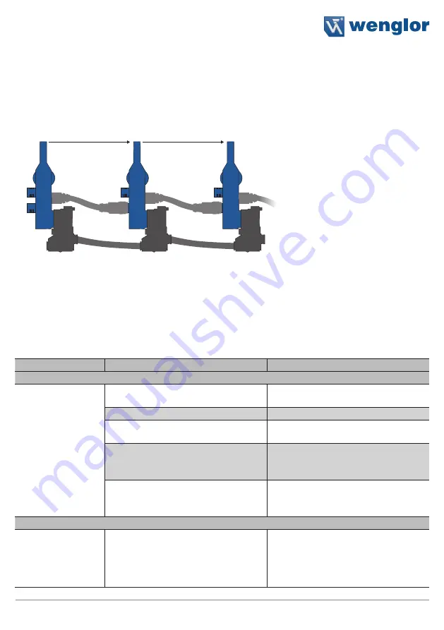
The sensors are connected to each other in series using the M12 cables (see figure 1). The maximum num-
ber of sensors which can be operated in a single chain depends on the utilized power supply. The direction of
conveyance must be taken into consideration in this respect.
Supply power can be fed to plug
(pins 1 and 3) at any point within the chain. Alternatively, supply power
can be fed via plug
(pins 1 and 3). However, supply power is normally connected at the end of the chain.
single discharge (pin 2) or block discharge (pin 4) can be activated at the end of the chain via plug
.
I/O
➂
➂
➃
➄ ➃
➂
➄
➄
➃
CHAIN
Conveyor direction
Conveyor direction
Image 1
It’s also possible to freely assign various functions to pins I/O1 und I/O2 via plug
.
See
section “7.2 Setting Inputs and Outputs”, page 25
with regard to configuring the pins.
5.3 Diagnostics
The following diagnosis functions are detected:
Indicator LED
Diagnosis/Cause
Elimination
Device malfunctions
Continuous blinking
at approx. 8 Hz
Contamination
Carefully clean the emitter and the
receiver with a cloth.
Aged emitter diode
Replace the device.
Short Circuit
Check electrical wiring and eliminate the
short-circuit.
• Solenoid valve connected incorrectly
• Solenoid valve defective
• Check electrical connection of the
solenoid valve to the sensor.
• Replace the solenoid valve.
Unreliable working range
• Increase sensing distance.
• Reduce distance between the sensor
and the object.
Process error
Material jam detected
Clear material jam so that accumulation
logic continues:
• Clear by means of block discharge
• Clear by means of manual removal
of the jam


