background image

21

When the module is assembled, recheck the door seals.

1.  Pull the door closed slowly while standing inside the room (outside the room for in-swinging doors).

2.  Watch the magnetic gasket as it makes contact with the door stop on the hinge side.

a.  If the gasket is squeezed and distorted, the door stop is too close to the door.

b.  If the door closes and the gasket is not completely sealed, the door stop must be adjusted 

closer.

iNSTallaTiON


CONTiNuEd

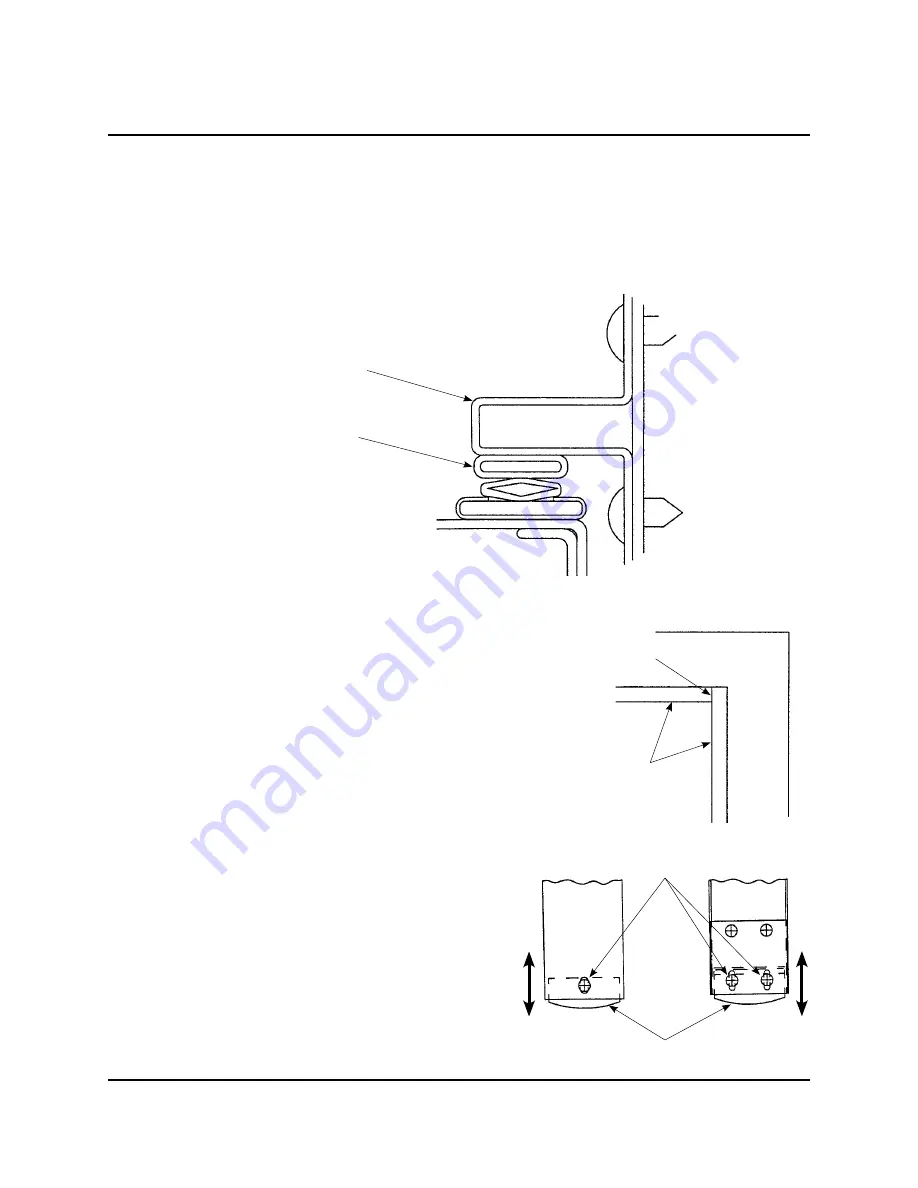
door seal adjustment

To adjust the Door Stop:

1.  Loosen the door stop screws slightly and move the stop in 

the proper direction.

2.  The magnetic gasket should jump slightly to the door stop 

when it is adjusted correctly.

3.  Tighten the screws and check upper corners of the door 

stop to see if the soft sealant is still sealing the joint 

between the vertical and horizontal door stop.

Remove the protective masking from the threshold and 

check the sweep seal on the bottom of the door and 

make sure that it is sealed.

1.  This seal should compress slightly when closing the 

door.

2.  This adjustment is made by loosening the three 

screws located on the ends.

3.  Readjust the height and tighten the three screws.

Door Seal Detail

Door Stop

Magnetic Gasket

Door Stops

Joint Soft Sealant

Screws

Bottom Seal

Summary of Contents for V-Ready

Page 1: ...Door Frame 6 Level the Wall Frame 9 Wall Panel installation 10 Roto Locks 10 Wall Panel Alignment 11 Install Corners 11 Assemble the Fan Panel 12 Assemble the Vent Panel 12 Ceiling Frame Rail with mo...

Page 2: ...5 16 Hex Wrench Pry Bar Socket and Ratchet Set 1 8 Drill Bit Phillips Drive Bit Cordless Drill Hacksaw Tools needed for Floor Option Owner___________________________ Models __________________________...

Page 3: ...prewired unit Wenger Corporation always ships the end user kits UL Power Panel Kit part number 216_481 before shipping the V Ready Room system A licensed electrician must install the Power Panel Kit B...

Page 4: ...A licensed electrician must install all distribution connections for the electrical service shown in the unit plan 2 Clear the construction area and allow twelve inches of space around the module 3 Pl...

Page 5: ...frame section As the pad is slightly longer than the channel each section should slightly compress the pad when clips are installed Drive the clips into place with a mallet Note Drive on clips so tha...

Page 6: ...arning The Door Frame Assembly weighs more than 250 pounds Four people working together must lift the assembly from the crate and set it into place Failure to observe this warning can result in seriou...

Page 7: ...mate with the Wall panels are plumb 6 If the Frame is not plumb carefully tilt the Frame to allow access to the Levelers a Start with the Levelers retracted as far as possible b On the corner that is...

Page 8: ...attach the Wall Frame to the Door Frame with the Offset Door Clips The narrower Wall Frame must be centered on the Door Frame Note The Offset Door Clips will only fit one way install the door frame co...

Page 9: ...crew clockwise to lift the Wall Frame and counterclockwise to lower the Wall Frame until the entire Frame is level Note Each Leveling Screw must contact the Wall Frame Pad Assembly c The rubber pad un...

Page 10: ...of the panel the Roto Lock Hole must always be on the left inside edge of the Panel wall panel installation installation continued Roto Lock Hole Centering Studs Panel Bottom Edge Panel Inside Surfac...

Page 11: ...y in size and appear to be uneven b Look under each Wall Panels and make sure of a seal to the Wall Frame If there is light the Panel is not sealed c If a gap is evident between a Wall Frame and Wall...

Page 12: ...nel with the screws from the hardware bag 8 The panel is now ready to be installed as a wall panel in the module assemble the fan panel installation continued Screws Fan Connector Cord Align with hole...

Page 13: ...with an eight inch diameter oval adapter that fits to eight inch diameter flex ducting 1 Place the Vent to HVAC Plenum over the wall vent panel outside opening with the Vent to HVAC Plenum Oval Adapt...

Page 14: ...ace the ceiling rails on top of wall panels with the 1 3 4 inch lip to the outside and facing upward The formed channel hangs down inside the module 4 Start at a corner and work completely around the...

Page 15: ...g joints at the corners 2 Attach the bolts finger tight through ceiling frames into wall panels install ceiling frame rails continued installation continued 3 Corner pieces and spacers have metal tabs...

Page 16: ...el on the module s interior 2 All rails corners and spacer joints must fit together perfectly If they do not the frame will not be square and will need readjusting The most important factor is that no...

Page 17: ...o locks and the other panel must have two female roto locks Use a Phillips screwdriver to make these changes Then install ceiling end panels so the one with female roto locks will be matched with male...

Page 18: ...ling panels now in place and locked together the ceiling system needs to be locked to the wall structure Remove the stack of angles ceiling clips and short tubular pieces clip retainers from the hardw...

Page 19: ...every 15 inches to match pattern of clips on ends of ceiling panels At all four corners place one clip in each direction but within the first 7 1 2 inches of corner for proper seal Do not place a clip...

Page 20: ...door stop A door stop bumper is provided with each module taped to the outside of the door leverset Select the location of the mounting by opening the door and choosing the locations you want to prev...

Page 21: ...ws slightly and move the stop in the proper direction 2 The magnetic gasket should jump slightly to the door stop when it is adjusted correctly 3 Tighten the screws and check upper corners of the door...

Page 22: ...power panel Then connect light to light If fans are used plug in connector cables for the fan panel closest to the power panel Then connect fan to fan Connect the house service connector cable from po...

Page 23: ...only 2 Place this side flush against the wall frame The female lock side or end of panels must be away from the door to avoid interference with the threshold plate floor installation 1 Keeping male lo...

Page 24: ...orary spacer jig b Press the angle firmly onto the threshold 2 Located upper angle so that the vertical leg is approximately 1 16 inch in front of the vertical member of the lower angle 3 Mark holes o...

Page 25: ...eeded Note Foam strip on back of molding should be compressed slightly to seal to wall Do not allow the metal molding to contact the wall Add the remaining molding and screw in place Slightly miter cu...

Page 26: ...ion Optional A ventilation grille painted oyster approximately 8x13 1 2 added to closure install the horizontal closure panels Horizontal Wood Closure 8 feet 4 inches from the floor to the bottom edge...

Page 27: ...coverage from module ceiling rail to floor cut to fit at installation Optional A ventilation grille painted oyster approximately 8 x13 1 2 added to closure Steel 2x4 approximately 87 inches in length...

Page 28: ...between the door stop and gasket perform steps C through F Sweep Seal Gasket at bottom of the door adjust only as necessary 1 Loosen two screws at sweep on latch side and one screw at sweep on the hi...

Page 29: ...om disassembly j Replace separators be sure thin wires are between rubber around windows and frame or door these wires keep the separators from bowing out at the center k Clean glass with glass cleane...

Page 30: ...nd or latch side of door It will help to fold the flange seal foam up and out of the way to ease pulling sweep seal from door This will also ease installing a new seal 3 Reverse this process to replac...

Page 31: ...e only 1 0A 120V AC 60 Hz Inrush Current 20A maximum for 2 milliseconds Time to Steady State 10 milliseconds Interior outlets maximum amperage per power panel available is 10 amps C Floor Load Capacit...

Page 32: ...LEVERSET Handle with lock DOOR SEAL Magnetic gasket on door leaf DOOR STEP TRIM Metal plates used to protect floor edging at doorway DOOR STOPS Channel that the magnetic gasket seals against in door...

Page 33: ...d alignment TRIM MOLDING Metal angle to finish off module at floor to wall at base WALL FRAME Channel with sound seal and leveling adjusters Makes up module foundation WALL FRAME CLIPS Metal C shaped...

Page 34: ...Electrical Audio 15 Microphone Wall Panel 15 Window Wall Panel Room Interior 30 Window Wall Pane Right hand reverse out swing Left hand in swing Left hand reverse out swing Right hand in swing 115V 20...

Page 35: ...oduct don t hesitate to call even if the product is past warranty It s important to us that all our customers be satisfied This is the sole warranty made by Wenger Wenger disclaims all other warrantie...

Page 36: ...This page is intentionally blank 36...

Reviews: