background image

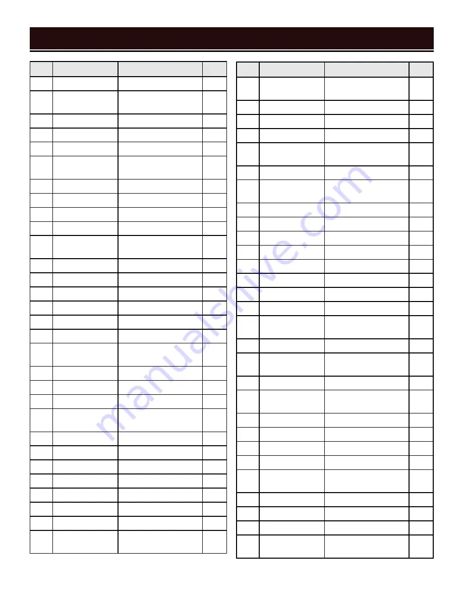
EXPLODED VIEW & PARTS LIST

No.

Part No.

Description

Qty.

60

3975-060

Driven Wheel

1

61

3975-061

Flat Head Screw, 

M8x12

1

62

3975-062

Key, 4x4x20mm

1

63

3975-063

Drive Wheel

1

64

3975-064

Flat Washer

1

65

3975-065

Flat Head Screw, 

M6x12

1

66

3975-066

Frame

1

67

3975-067

Spring Washer

8

68

3975-068

Blade Tension Knob

1

69

3975-069

Cord Clamp

2

70

3975-070

Pan Head Screw, 

M5x8

2

71

3975-071

Set Screw, M6x8

1

72

3975-072

Lock Handle

1

73

3975-073

Flat Washer, 6mm

1

74

3975-074

Nut, M6

4

75

3975-075

Lock Washer, 6mm

4

76

3975-076

Flat Washer, 6mm

4

77

3975-077

Rear Blade Guide 

Block

1

78

3975-078

Ball Bearing, 625ZZ

2

79

3975-079

Flat Washer, 5mm

4

80

3975-080

Pin, 5x24mm

1

81

3975-081

Socket Head Screw, 

M6x25

1

82

3975-082

Lock Washer, 6mm

1

83

3975-083

Blade Guard

1

84

3975-084

Flat Washer, 6mm

4

85

3975-085

Ball Bearing, 607ZZ

8

86

3975-086

Shaft

4

87

3975-087

Flat Washer, 6mm

2

88

3975-088

Lock Washer, 6mm

2

89

3975-089

Socket Head Screw, 

M6x25

2

No.

Part No.

Description

Qty.

90

3975-090

Socket Head Screw, 

M5x10

1

91

3975-091

Flat Washer, 5mm

1

92

3975-092

Guard Plate

1

93

3975-093

Pin, 5x35mm

1

94

3975-094

Front Blade Guide 

Block

1

95

3975-095

Nut, M6

1

96

3975-096

Socket Head Screw, 

M6x25

1

97

3975-097

Nut, M16-1.5

1

98

3975-098

Center Shaft

1

99

3975-099

Torsion Spring

1

100

3975-100

Lock Handle

1

101

3975-101

Flat Washer, 10mm

1

102

3975-102

Swivel Support

1

103

3975-103

Flat Washer, 12mm

1

104

3975-104

Nut, M12

1

105

3975-105

Hex Head Bolt, 

M6x25

1

106

3975-106

Nut, M6

1

107

3975-107

Socket Head Screw, 

M6x35

1

108

3975-108

Flat Washer, 6mm

1

109

3975-109

Socket Head Screw, 

M5x10

2

110

3975-110

Positive Stop Cam

2

111

3975-111

Bushing

1

112

3975-112

Retaining Ring, 8mm

1

113

3975-113

Lock Pin

1

114

3975-114

Pan Head Screw, 

M4x8

2

115

3975-115

Angle Scale

1

116

3975-116

Base

1

117

3975-117

Foot

4

118

3975-118

Carriage Bolt, 

M10x40

1

18

Summary of Contents for BA4555

Page 1: ...d trouble free performance Pay close attention to the rules for safe operation warnings and cautions If you use your tool properly and for its intended purpose you will enjoy years of safe reliable service NEED HELP CONTACT US Have product questions Need technical support Please feel free to contact us TECHSUPPORT WENPRODUCTS COM 1 800 232 1195 M F 8AM 5PM CST For replacement parts and the most up...

Page 2: ... Know Your Metal Band Saw 10 Assembly Adjustments 11 2 CONTENTS WELCOME 3 Introduction 3 Specifications 3 SAFETY 4 General Safety Rules 4 Specific Rules for Your Metal Band Saw 6 Electrical Information 8 BEFORE OPERATING OPERATION MAINTENANCE To purchase accessories for your tool visit WENPRODUCTS COM Replacement Blades Model BB5650 ...

Page 3: ... most up to date manual or contact our customer service at 1 800 232 1195 Keep this manual available to all users during the entire life of the tool and review it frequently to maximize safety for both yourself and others SAFETY ALERT SYMBOL Indicates danger warning or caution The safety symbols and the explanations with them deserve your careful attention and understanding Always follow the safet...

Page 4: ...c shock PERSONAL SAFETY 1 Stay alert watch what you are doing and use com mon sense when operating a power tool Do not use a power tool while you are tired or under the influence of drugs alcohol or medication A moment of inatten tion while operating power tools may result in serious personal injury 2 Use personal protective equipment Always wear eye protection Protective equipment such as a respi...

Page 5: ...accordance with these instructions taking into ac count the working conditions and the work to be per formed Use of the power tool for operations different from those intended could result in a hazardous situa tion 8 Use clamps to secure your workpiece to a stable surface Holding a workpiece by hand or using your body to support it may lead to loss of control 9 KEEP GUARDS IN PLACE and in working ...

Page 6: ... your health Use NIOSH ap proved dust masks or other respiratory protection dur ing operation and cleaning 6 Always turn off and unplug the metal band saw be fore making any adjustments or repair tasks Never ad just the metal band saw or the workpiece while the saw is running PREPARING THE METAL BAND SAW 1 When transporting the metal band saw never carry the device by its guards or its accessories...

Page 7: ...e guide supports bearings and blade tension must be properly adjusted to avoid accidental blade contact and to minimize blade breakage To maximize blade support always adjust the upper blade guide and blade guard so that it barely clears the workpiece 8 Turn on the band saw and let it reach full speed then slowly slide the workpiece into the blade This will help produce safer and cleaner cuts 9 Ne...

Page 8: ...of the equipment grounding conductor can result in electric shock The conductor with the green insulation with or without yellow stripes is the equipment grounding conductor If repair or replacement of the electric cord or plug is necessary DO NOT connect the equipment grounding conductor to a live terminal 1 Examine extension cord before use Make sure your extension cord is properly wired and in ...

Page 9: ...e all of the parts and accessories If any part is missing or broken please contact our customer service at 1 800 232 1195 M F 8 5 CST or email techsupport wenproducts com PACKING LIST UNPACKING PACKING LIST WARNING Do not plug in or turn on the tool until it is fully assembled according to the instructions Failure to follow the safety instructions may result in serious personal injury 9 Metal Band...

Page 10: ...become familiar ized with all the parts and controls of your metal band saw The components will be referred to later in the manual for assembly and operation instructions 10 Power Switch Run Trigger Blade Tensioning Knob Blade Guide Lock Vise Handle Rubber Feet Variable Speed Knob Circuit Breaker Locking Pin Miter Locking Handle Work Stop ...

Page 11: ...he locking handle is spring loaded and can be re positioned as need be To re position the handle pull it out wards turn it to the desired position and release it POSITIONING THE WORK STOP If you have to make a series of cuts with a uniform length use the supplied work stop 1 Loosen the lock handle Fig 4 1 2 Slide the work stop to the desired distance 3 Tighten the lock handle again WARNING Do not ...

Page 12: ...ry blade guide assembly so that its side lays flush with the body of the saw 3 Tighten the screws SLIDING BLADE GUIDE The blade guide must be adjusted before every cut on a workpiece Without proper adjustment the resulting cut may be unclean or jagged 1 Loosen the blade guide locking handle Fig 7 1 2 Slide the blade guide to move it closer to the workpiece Position the guide bearings as close to t...

Page 13: ...lade has come to full speed gradually lower the saw body downwards until the blade comes into light contact with the workpiece Let the saw blade make a small groove along the workpiece to help ensure a straight cut particularly with curved or round workpieces 5 Once initial contact and a groove have been made apply a small amount of additional pressure to continue the cut Let the machine do the wo...

Page 14: ...lade about 1 8 in 6 Replace the blade cover and install the six screws Fig 13 7 Run the saw at no load for 10 20 seconds to allow the blade to seat on the wheels 8 Adjust the blade guide in preparation for the next cut GENERAL MACHINE CARE 1 Routinely check the condition of the power supply cords and replace them if they are broken worn or if internal wires are showing 2 Use a brush to remove chip...

Page 15: ...lade guide alignment Ensure sliding blade guide is positioned as close to workpiece as pos sible 4 Adjust blade speed 5 Clamp workpiece securely Ensure vise jaws and vise ways are clean Use work stop to stabilize workpiece 6 Adjust blade tension Fig 14 1 The blade tends to protrude from the guide or keeps pop ping off 1 Excessive blade tension 2 Blade is slipping on wheels or guide bearings due to...

Page 16: ...EXPLODED VIEW PARTS LIST 16 ...

Page 17: ...2 26 3975 026 Retaining Ring 35mm 2 28 3975 028 Ball Bearing 607ZZ 2 29 3975 029 Retaining Ring 11mm 1 No Part No Description Qty 30 3975 030 43T Gear 1 31 3975 031 Key 4x4x6mm 1 32 3975 032 Pinion Gear 1 34 3975 034 Socket Head Screw M8x25 4 35 3975 035 Flat Washer 8mm 4 36 3975 036 Gearbox 1 37 3975 037 Blade Cover 1 38 3975 038 Pan Head Screw M5x8 6 39 3975 039 Flat Washer 5mm 6 40 3975 040 Lef...

Page 18: ...7ZZ 8 86 3975 086 Shaft 4 87 3975 087 Flat Washer 6mm 2 88 3975 088 Lock Washer 6mm 2 89 3975 089 Socket Head Screw M6x25 2 No Part No Description Qty 90 3975 090 Socket Head Screw M5x10 1 91 3975 091 Flat Washer 5mm 1 92 3975 092 Guard Plate 1 93 3975 093 Pin 5x35mm 1 94 3975 094 Front Blade Guide Block 1 95 3975 095 Nut M6 1 96 3975 096 Socket Head Screw M6x25 1 97 3975 097 Nut M16 1 5 1 98 3975...

Page 19: ... 3975 132 Set Screw M5x8 1 133 3975 133 Guide Block 1 19 No Part No Description Qty 134 3975 134 Lock Washer 6mm 1 135 3975 135 Hex Head Bolt M6x25 1 137 3975 137 Lock Washer 8mm 6 138 3975 138 Socket Head Screw M8x25 6 139 3975 139 Nut M12 1 140 3975 140 Work Stop Rod 1 141 3975 141 Work Stop 1 142 3975 142 Lock Handle 1 143 3975 143 Hex Head Bolt M6x25 1 144 3975 144 Toothed Washer 8mm 1 145 397...

Page 20: ...fective parts and products may need to be sent to WEN before the replacements can be shipped out Upon the confirmation of a WEN representative your product may qualify for repairs and service work When re turning a product for warranty service the shipping charges must be prepaid by the purchaser The product must be shipped in its original container or an equivalent properly packed to withstand th...

Reviews: