


9
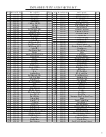
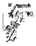
EXPLODED VIEW AND PARTS LIST
No. Part Number
Description
Qty.
1
6369-001
M6X15 Screw
1
2
6369-002
Ø
6 Washer
1
3
6369-003
Sanding Pad
1
4
6369-004
Output Shaft
1
5
6369-005
Flat Key 3X3X10
1
6
6369-006
Oil Seal
1
7
6369-007
Collar
Ø
22
1
8
6369-008
Ball Earing 6900 Rs
1
9
6369-009
Screw M4*12
6
10
6369-010
Big Bearing Cover
1
10A
6369-011
Paper Washer
1
11
6369-012
End Gear
1
12
6369-013
Collar
Ø
10
1
13
6369-014
Ball Bearing 606 Z
2
15
6369-015
Small Bearing Cover
1
16
6369-016
Ball Bearing 699 Z
1
16A
6369-017
Collar
Ø
22
1
17
6369-018
Main Driving Shaft
1
17A
6369-019
Washer
1
18
6369-020
Semi-Circular Key 3X3X10
1
19
6369-021
Tapered Gear
1
19A
6369-022
Washer
1
20
6369-023
Collar
Ø
9
1
21
6369-024
Gear Box
1
22
6369-025
Middle Cover
1
22A
6369-026
Spring Of Rotor
1
22B
6369-027
Wool Cap
1
23
6369-028
Rotor
1
23A
6369-029
Anti-Dust Ring
1
24
6369-030
Ball Bearing 607 Rs
1
25
6369-031
Anti-Wind Ring
1
26
6369-032
Screw St4*55
2
26A
6369-033
4.2 Circular Button
1
27
6369-034
Stator
1
27A
6369-035
Sleeve
1
28
6369-036
Motor Housing
1
28A
6369-037
Ø
4 Flat Washer
4
28B
6369-038
Ø
4 Flexible Washer
4
29
6369-039
Screw M4*20
4
30
6369-040
Brush Holder
2
31
6369-041
Carbon Brush
2
32
6369-042
Screw St3*10
4
33
6369-043
Coil Spring
2
34
6369-044
Back Cover
1
34A
6369-045
Screw St4*12
2
35
6369-046
Screw St4*14
42
36
6369-047
Pressing Block On Motor Housing
1
37
6369-048
Vibration Damping
2
38
6369-049
Big Rubber Sleeve
2
39
6369-050
Screw Pin
2
40
6369-051
Flexible Sleeve
1
41
6369-052
Brush Segment
1
No. Part Number
Description
Qty.
42
6369-053
Sanding Pad Cover
1
48
6369-054
Tightening Ring 25-38
1
49
6369-055
350 Hose
1
50
6369-056
Small Cable Sleeve
1
51
6369-057
Small Rubber Cover
2
52
6369-058
Right Handle Stand
1
53
6369-059
Ø
28 Connector
2
54
6369-060
Plastic Soft PipeØ28
1
55
6369-061
Ellipticle Connector
1
57
6369-062
Left Handle Stand
1
58
6369-063
Washer
Ø
4
4
59
6369-064
Compressed Spring
4
60
6369-065
Electric Sensor
2
61
6369-066
Cable Plate
2
62
6369-067
Electric Capacity
1
63
6369-068
Electronic Speed Control Plate
1
64
6369-069
Potentiometer
1
65
6369-070
Speed Button
1
67
6369-071
Cable
1
68
6369-072
Cable Sleeve
1
69
6369-073
Left Main Handle
1
70
6369-074
Aluminium Pipe Insert
1
71
6369-075
Cable Pressing Plate
1
72
6369-076
Left Sub-Handle
1
73
6369-077
Aluminium Pipe
1
73A
6369-078
Back Hinge Sleeve
1
73B
6369-079
Ø
5X45Pin
1
73C
6369-080
Ø
5 Clinch Bolt
2
73D
6369-081
Ø
1.2 Sealed Ring
1
73E
6369-082
Front Hinge Sleeve
1
73F
6369-083
Aluminium Pipe
1
73M
6369-084
Supporting Arm
2
73P
6369-085
Pin
Ø
5X30
1
73Q
6369-086
Pin
Ø
5X16.8
1
73H
6369-087
Sleeve 2#
1
73I
6369-088
Front Latch
1
73J
6369-089
Spring
1
73K
6369-090
Latch Pivot
1
73L
6369-091
Fixed Plate
1
74
6369-092
Aluminium Pipe With Single Access
1
75
6369-093
Switch
1
76
6369-094
Switch Pushing Lever
1
77
6369-095
Switch Button
1
78
6369-096
Right Sub-Handle
1
79
6369-097
Circular Pin
Φ
1.5X11.8
1
80
6369-098
Back Screw Nut
2
81
6369-099
Right Main Handle
1
82
6369-100
Hose Connection Adapter
1
83
6369-101
Adjustable Ring
1
84
6369-102
Connection Adapter
1
/
6369-103
Flexible Hose
1
/
6369-104
Dust Port Connection Adapter
1
Summary of Contents for 6369
Page 10: ...10 EXPLODED VIEW AND PARTS LIST...
Page 12: ...Thanks for remembering...


