background image

17

16

CAUTION! Saw blades are sharp. Always wear 

ANSI Z87.1-approved eye protection, as well as 

protective gloves, while handling saw blades.

CAUTION! Always be sure that the band saw 

is turned OFF and unplugged before making any 

adjustments.

OPERATION

Fig. 22 

GENERAL CUTTING GUIDELINES

1. Make a test cut on scrap wood to test the settings and 

get the hang of operating the band saw.

2. Make all adjustments with the band saw turned OFF 

and unplugged.

3. Make sure the upper guard is close to the upper face 

of your workpiece (see Adjusting the Upper Blade Guide 

on page 14). Always use a push stick when cutting in-

tricate or narrow workpieces. Keep fingers, hands, and 

other beloved body parts away from the blade!

4. Do not force the workpiece against the blade. Let the 

tool do the work. Light contact gives easier cutting and 

prevents excess friction, which will prolong the life of 

the blade and prevents workpiece burning.

5. Always use dust collection. A dust port is located on 

the back of the saw, next to the motor (p. 10 - O). Use a 

hose clamp (if necessary) to secure the adapter or dust 

hose to the dust port.

6. The band saw is most suitable for straight-line cut-

ting (cross-cutting, ripping, miter cutting, beveling, 

compound cutting, and resawing). While it can certainly 

cut curves, it is not a scroll saw, and cannot perform the 

same kinds of cuts. Do not cut sharp corners; instead, 

saw around corners.

CUTTING CURVES

When cutting curves, carefully turn the workpiece so 

that the blade follows the cut line without twisting. If the 

curve is so sharp that you repeatedly back up and cut 

new kerf, use a narrower blade, or a blade with more set 

(that is, the teeth are further apart). When a blade has 

more set, the workpiece turns more easily, but you will 

get a rougher cut.

When changing a cut, do not withdraw the workpiece 

from the blade – the workpiece may drag the blade off 

the wheels. Instead, turn the workpiece and cut out 

through the scrap section of the workpiece. When cut-

ting long curves, make relief cuts as you go along.

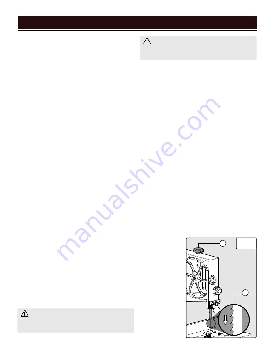
CHANGING BLADES (FIG. 22)

1. Double-check that the band saw is turned OFF and 

disconnected from the power source. Open the upper 

and lower doors.

2. Loosen the four guide rail lock knobs (you do not 

have to completely remove the knobs), and slide the 

guide rail off. 

3. Turn the blade tension knob (A) to relieve tension on 

the blade.

4. Remove the blade from the wheels and from between 

the upper and lower bearing guides. Guide it through 

the table slot. Store the blade in a safe place.

5. Guide the new blade through the table slot, spine 

first. The blade teeth should be facing you, pointing 

down towards the table (B).

6. Place the blade on the upper and lower wheels, and 

between the bearing guides.

7. Tension the blade (see Adjusting the Blade Tension 

on page 14).

8. Adjust the blade tracking (see Adjusting the Blade 

Tracking on page 13).

9. Adjust the upper 

and lower bearing 

guides (see   on 

page 14 - 15).

10. Replace the 

guide rail. Tighten 

the lock knobs.

11. Make a test cut 

on a scrap piece 

of wood before 

resuming cutting.

B

A

Summary of Contents for 3962

Page 1: ...le free performance Pay close attention to the rules for safe operation warnings and cautions If you use your tool properly and for its intended purpose you will enjoy years of safe reliable service NEED HELP CONTACT US Have product questions Need technical support Please feel free to contact us TECHSUPPORT WENPRODUCTS COM 1 800 232 1195 M F 8AM 5PM CST For replacement parts and the most up to dat...

Page 2: ...OPERATING 9 Unpacking Transportation 9 Know Your Band Saw 10 Assembly Adjustments 11 OPERATION MAINTENANCE 16 Operation 16 Maintenance 18 Troubleshooting Guide 19 Exploded View Parts List 21 Warranty Statement 25 To purchase accessories for your tool visit WENPRODUCTS COM Replacement Blades visit our website for our full line of 72 inch band saw blades ...

Page 3: ...ucts com for the most up to date manual or contact our customer service at 1 800 232 1195 Keep this manual available to all users during the entire life of the tool and review it frequently to maximize safety for both yourself and others SAFETY ALERT SYMBOL Indicates danger warning or caution The safety symbols and the explanations with them deserve your careful attention and understanding Always ...

Page 4: ...c shock PERSONAL SAFETY 1 Stay alert watch what you are doing and use com mon sense when operating a power tool Do not use a power tool while you are tired or under the influence of drugs alcohol or medication A moment of inatten tion while operating power tools may result in serious personal injury 2 Use personal protective equipment Always wear eye protection Protective equipment such as a respi...

Page 5: ...accordance with these instructions taking into ac count the working conditions and the work to be per formed Use of the power tool for operations different from those intended could result in a hazardous situa tion 8 Use clamps to secure your workpiece to a stable surface Holding a workpiece by hand or using your body to support it may lead to loss of control 9 KEEP GUARDS IN PLACE and in working ...

Page 6: ...oves neckties jewelry or loose clothing while operating the saw 5 Saw dust is harmful to your health Use NIOSH ap proved dust masks or other respiratory protection dur ing operation and cleaning 6 Always turn off and unplug the band saw before mak ing any adjustments or repair tasks Never adjust the band saw or the workpiece while the saw is running 7 Only use the band saw to cut wood PREPARING TH...

Page 7: ...e the band saw unless all guards are in place Do not operate with any guard disabled dam aged or removed Moving guards must move freely and close instantly 7 Blade guide supports bearings and blade tension must be properly adjusted to avoid accidental blade contact and to minimize blade breakage To maximize blade support always adjust the upper blade guide and blade guard so that it barely clears ...

Page 8: ...tor with the green insulation with or without yellow stripes is the equipment grounding conductor If repair or replacement of the electric cord or plug is necessary DO NOT connect the equipment grounding conductor to a live terminal 1 Examine extension cord before use Make sure your extension cord is properly wired and in good condition Always replace a damaged extension cord or have it repaired b...

Page 9: ...he tools listed below are required for either assembly or adjustment 14mm Open End Wrench 2 Phillips Head Screwdriver 1 UNPACKING TRANSPORTATION WARNING Do not plug in or turn on the tool until it is fully assembled according to the instructions Failure to follow the safety instructions may result in serious personal injury 9 Band Saw Table 1 Guide Rail 1 Legs 4 Miter Gauge 1 Long Brace 2 Short Br...

Page 10: ...and operation instructions A Light On Off Switch B Power Switch C Fence Assembly D Fence Locking Lever E Lower Housing Knob F Miter Gauge G Upper Blade Guide H Blade Bearing Adjustment Knob I Blade Guide Adjustment Knob J Upper Housing Knob K Blade Tension Knob L Blade Tracking Adjustment Knob M Work Light N Table Bevel Lock O Dust Port P Motor Q Motor Tension Release Hex Bolt R Tracking Lock Knob...

Page 11: ... D and long F braces to the legs with the M8x16 carriage bolts 8mm flat washers and M8 hex nuts B Hand tighten NOTE Do not fully tighten the nuts yet NOTE It is best to attach the table in the 0 position perpendicular to the blade If desired you may bevel the table in order to access the bolts more easily 4 Attach a rubber foot E to each leg 5 Place the saw upright Use the bubble level on the base...

Page 12: ... the fence beam C 3 Re install the knobs A and washers B onto the fence beam bolts D Tighten the knobs ASSEMBLY ADJUSTMENTS 12 NOTE When cutting thin materials the fence may be re positioned further See Fig 8 Remove the knobs A and washers B from the fence assembly Flip the fence so the flat side faces down Remove the fence beam bolts and re install them in the bottom slot C Re install the knobs a...

Page 13: ...he saw body E then tighten the nut ADJUSTING THE BLADE TRACKING Blade tracking refers to the adjustments that are made in order to keep the blade riding on the wheels smoothly and evenly Blade tracking has been set by the factory However when you install a new blade you may need to adjust the tracking settings 1 Turn off and unplug the band saw Wait for the blade to come to a complete stop Open th...

Page 14: ...ch ADJUSTING THE UPPER BLADE GUIDE FIG 14 The height of the upper blade guide should be adjusted prior to every cut The blade guide should always be posi tioned as close to the upper face of the workpiece as pos sible no more than 1 8 inch 3mm away 1 Loosen the adjustment locking knob B Use the adjust ment knob outer ring A to adjust the height of the upper blade guide Tighten the adjustment locki...

Page 15: ...revent blade drift Fig 18 Fig 17 WARNING The lower blade guide bearings must be adjusted after every blade change and tracking adjustment 1 Turn off and unplug the band saw Wait for the blade to come to a complete stop Open the lower door 2 Use a hex wrench to loosen the socket head cap screw D found beneath the table insert Position the assembly so that the roller bearings are about 1 2 mm 1 10 i...

Page 16: ...on the back of the motor mounting flange and return the motor to its original position The weight of the motor will apply tension to the drive belt Press on the inside of the belt with a finger if the belt moves about inch the belt is properly tensioned Tighten the screw Close the lower cover NOTE Use the instructions above to adjust the belt tension as needed over the life of your saw Older belts...

Page 17: ... cutting curves carefully turn the workpiece so that the blade follows the cut line without twisting If the curve is so sharp that you repeatedly back up and cut new kerf use a narrower blade or a blade with more set that is the teeth are further apart When a blade has more set the workpiece turns more easily but you will get a rougher cut When changing a cut do not withdraw the workpiece from the...

Page 18: ... these include but are not limited to gasoline carbon tetrachloride chlorinated cleaning solvents and household deter gents that contain ammonia 4 At least once a month check the V belt for proper tension and any signs of wear 5 Store the tool in a clean and dry place away from the reach of children Store in temperatures between 41 to 86 F 6 Cover the band saw in order to protect it from dust and ...

Page 19: ...ice 4 Bad motor bearing or bad motor 4 Stop using the tool and call 1 800 232 1195 for customer service LED light does not turn on 1 Band saw is not plugged in 1 Plug in saw 2 LED power switch turned OFF 2 Turn switch to ON I 3 Loose connection 4 Stop using the tool and call 1 800 232 1195 for customer service 5 Bad LED module or PCB 4 Stop using the tool and call 1 800 232 1195 for customer servi...

Page 20: ... 5 Adjust tracking properly See page 13 6 Improper feed rate 6 Do not force the workpiece Let the tool do the work 7 Blade is warped 4 Stop using the tool and call 1 800 232 1195 for customer service Saw is noisy 1 Loose fastener 1 Check the saw and stand and ensure that all fasteners are tightened 2 Guide bearings improperly adjusted 4 Adjust guide bearings properly See pages 14 15 3 Improper bla...

Page 21: ...21 EXPLODED VIEW PARTS LIST ...

Page 22: ...ket Head Bolt 1 32 3962 032 Serrated Washer 2 33 3962 033 Pan Head Screw 2 34 3962 034 Switch Box 1 No Part No Description Qty 35 3962 035 Connecting Terminal 2 36 3962 036 Switch Cover 1 37 3962 037 Led Switch 1 38 3962 038 Main Switch 1 39 3962 039 Pan Head Screw 2 40 3962 040 Nut 1 41 3962 041 Flat Washer 1 42 3962 042 Bushing 1 43 3962 043 Flat Washer 1 44 3962 044 Brush 1 45 3962 045 Carriage...

Page 23: ...2 626ZZ Ball Bearing 2 98 3962 098 Socket Head Bolt 2 99 3962 099 Socket Head Bolt 2 100 3962 100 Flat Washer 2 No Part No Description Qty 101 3962 101 Hex Nut 2 102 3962 102 Socket Head Bolt 2 103 3962 103 Set Screw 1 104 3962 104 Motor Pulley 1 105 3962 105 Belt 1 106 3962 106 Hex Head Bolt 4 107 3962 107 Motor Support Plate 1 108 3962 108 Flat Washer 2 109 3962 109 Socket Head Bolt 2 110 3962 1...

Page 24: ...62 151 Guide Rail 1 152 3962 152 Guide Rail Cap 1 153 3962 153 Thread Forming Screw 2 154 3962 154 Pointer 1 155 3962 155 Sliding Base 1 156 3962 156 Nut 3 157 3962 157 Spacer 1 158 3962 158 Socket Head Bolt 1 159 3962 159 Spring Plate 1 160 3962 160 Pan Head Screw 1 161 3962 161 Lock Block 1 162 3962 162 Lock Handle 1 163 3962 163 Shaft 1 164 3962 164 Hex Nut 16 165 3962 165 Flat Washer 16 166 39...

Page 25: ...ts and products may need to be sent to WEN before the replacements can be shipped out Upon the confirmation of a WEN representative your product may qualify for repairs and service work When re turning a product for warranty service the shipping charges must be prepaid by the purchaser The product must be shipped in its original container or an equivalent properly packed to withstand the hazards o...

Page 26: ...26 NOTES ...

Page 27: ...27 NOTES ...

Page 28: ...THANKS FOR REMEMBERING v 2019 09 20 ...

Reviews: