background image

CA1

CA2

CA3

CA4

SOURCE

RIGHT

REAR

LEFT

A/V

INPUT

SCAN

A/V ON/OFF

DIMMER 

EXIT 

WIDE 

SELECT 

SCAN-TIME 

TRIGGER 


PRIORITY 


DISPLAY 

MENU

SYSTEM

QUAD

OSD

AUTO POWER

WDRV-7464M/8464M 

  Function .9 

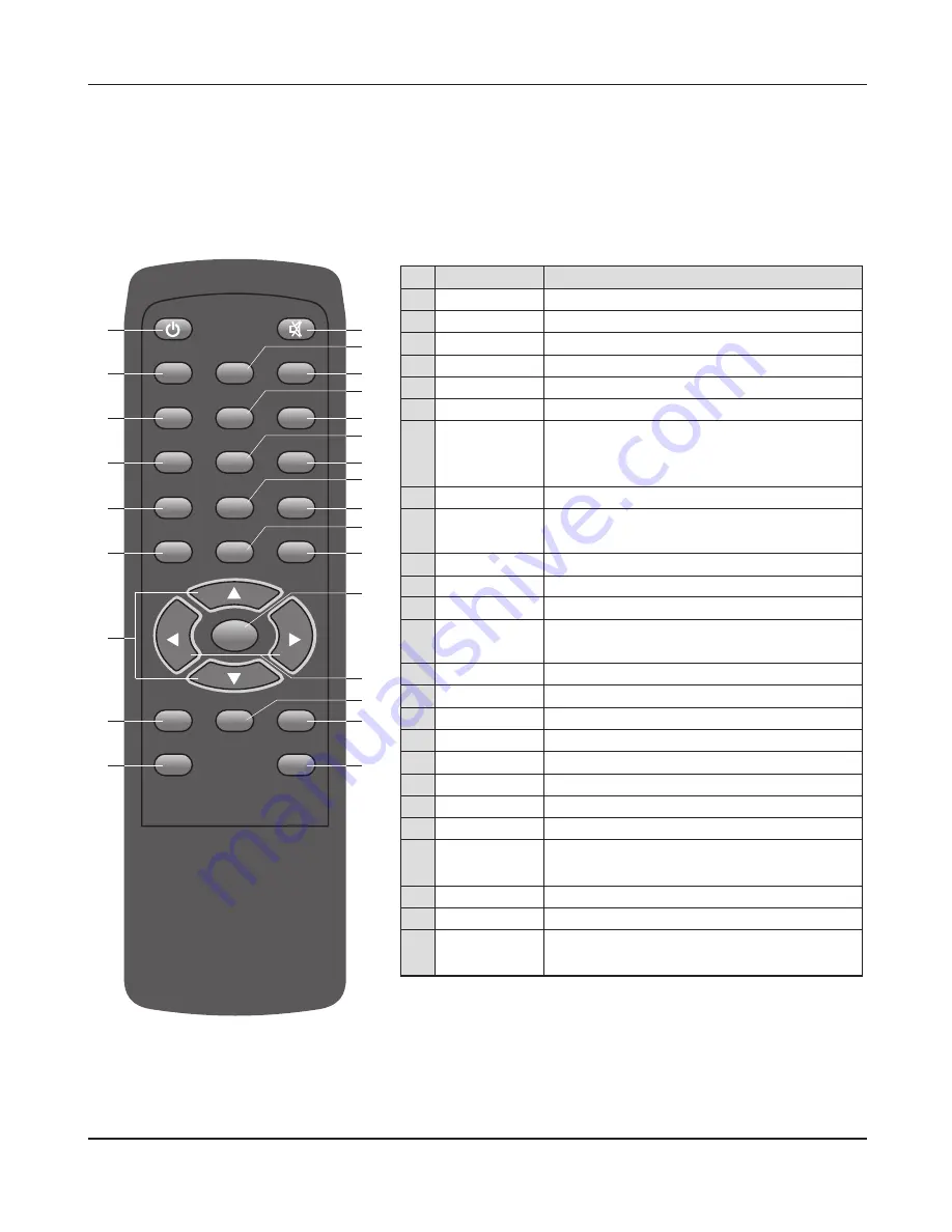
REMOTE CONTROL (Option)

1

2

3

4

5

6

7

8

9

10 

11 

12 

13 
14 

15 
16 

17 
18 

19 
20 

21 

22 

23 

24 

25 

No. 

  1 

  2 

  3 

  4 

  5 

  6 


  7 


  8 


  9 


10 

11 

12 


13 


14 

15 

16 

17 

18 

    19 

    20 

    21  


22 


    23   

     24   

      25 


Button 

POWER 

CA1  

CA2  

CA3  

CA4 

DIMMER 
UP/DOWN  

▲▼


EXIT 


SCAN TIME 


MUTE 

SOURCE 

AUTO POWER 


QUAD 


OSD 

SCAN 


SYSTEM 

A/V  ON/OFF 

DISPLAY 

MENU 


VOL


WIDE 

SELECT 

 TRIGGER 

 PRIORITY 


A/V 

  INPUT 

Description 

On/off power of LCD monitor 

Change camera1 video 

Change camera2 video 

Change camera3 video 

Change camera4 video 

Dimmer control button 

Use select items in the on screen menu, 

press UP/DOWN buttons to control rear view 

motorized camera only 

Turn menu off 

Scanning function up to 9 seconds for selected 

camera. 

Mutes sound 

Press to display only full screen mode available 

The power of LCD stays on/off 

Press to display half screen mode and quad 

screen mode. 

Sets operating OSD display 

Change A/V video 

Trigger in auto / normal function select 

Shows INPUT signal automatically  

None 

Audio/Video  ON/OFF  

Preset display mode 

Displays menu options on screen 

Adjusting the volume is available only when 

trigger input is done       

Picture ratio control (Wide/Normal)   

Press to display all available video source 

Sets priority video source when more than 

two trigger signals enter at the same time 


Summary of Contents for WDRV-7464M

Page 1: ......

Page 2: ...symbol within an equilateral triangle is intended to alert the user to the presence of dangerous voltage within a product s enclosure that may be of sufficient magnitude to constitute a risk of electr...

Page 3: ...nts 1 Table of Contents 2 Features Precautions 3 Packing List 4 Functions Monitor Remote Control 5 System Wiring 6 Installation 7 Operation 8 Troubleshooting 9 Specifications Dimensions 3 4 7 8 9 10 1...

Page 4: ...rmanently Regulatory Information This equipment has been tested is in compliance with the limits for a Class B digital device pursuant to part 15 of the FCC Rules These limits are designed to provide...

Page 5: ...mmediate attention include a lack of sound noxious smoke being emitted from the unit or foreign objects dropped inside the unit Do not use this equipment outside the vehicle Do not use this equipment...

Page 6: ...Service Never remove the back cover of the monitor this can expose you to high voltage and other hazards If the monitor does not operate properly unplug it and call your dealer Location Position your...

Page 7: ...WDRV 7464M 8464M Packing List 7 Packing List 2 Batteries Type AAA for Remote Controller Option Remote Controller Option Manual Set TFT LCD Monitor Sunshield Stand Bracket...

Page 8: ...nu press UP DOWN buttons to control front rear view motorized camera only Press select button to change video source and view mode If button is beld down over 1 second the setting will be changed to t...

Page 9: ...e camera3 video Change camera4 video Dimmer control button Use select items in the on screen menu press UP DOWN buttons to control rear view motorized camera only Turn menu off Scanning function up to...

Page 10: ...mera WDRV 3478C Side View Camera WDRV 3478C General Camera Side View Camera WDRV 3478C General Camera FEMALE MALE FEMALE MALE FEMALE MALE WDRV 3478C Pin Connection SIDE VIEW CAMERA 4 3 2 1 HOLE Pin No...

Page 11: ...an 5Kg 11 lbs Clean the surface before installation Remove the protective paper covering the bottom of the bracket Stick the provided bracket on the surface and fix it firmly with the screws Adjust th...

Page 12: ...lly selected input on mode TRIGGER TIME 800ms 1200ms 2000ms 2500ms 3000ms 1200ms Default TRIGGER PRIO Set the priority video source when more than two trigger signals enter at the same time AUTO MOTOR...

Page 13: ...ialization BRIGHT Adjust the brightness of the screen CONTRAST Adjust the contrast of the screen TINT Adjust the tint of the screen COLOR Adjust the color of the screen SHARPNESS Adjust the sharpness...

Page 14: ...WDRV 7464M 8464M Operation 14 E VIEW MODE 1 Single CAM 1 CAM 4 A V Dual Half CAM 1 CAM 2 CAM 3 CAM 4 Quad CAM 1 CAM 2 CAM 3 CAM4 CAM 1 or CAM 3 CAM 2 or CAM 4 CAM 1 CAM 3 CAM 2 CAM 4...

Page 15: ...WDRV 7464M 8464M Operation 15 F View Mode 2 Tacho function Option Use the CAM2 only Front View CAM2 Above 10Km h Display Off Power On Below 10Km h Display on CAM2 Off Mode...

Page 16: ...cho function Option Use the CAM1 CAM2 Front View CAM2 REAR View CAM1 Input from REAR TRIGGER Above 10Km h Split Display Start Below 10Km h CAM2 Display REAR View CAM1 FRONT View CAM2 Power On Split Di...

Page 17: ...M3 CAM4 Front View CAM2 REAR View CAM1 Input from LEFT RIGHT REAR TRIGGER Above 10Km h Quad Display Start Below 10Km h CAM2 Display REAR View CAM1 FRONT View CAM2 LEFT View CAM3 RIGHT View CAM4 Power...

Page 18: ...r A When the extension cable is too long diminishing of video may happen Resolution might decrease due to protection of LCD window Q Sync signal distracts and the screen is black and white A Change th...

Page 19: ...ode Q Auto scan does not operate A Scan does not operate when there is only one camera image Q Auto scan mode is too fast A Adjust S TIME in appropriate level in menu mode Q OSD disappears in the scre...

Page 20: ...TBF SIGNAL FEATURE POWER CONSUMPTION SIZE Width x Depth x Height POWER SOURCE TEMPERATURE DC 12V 32V TFT LCD COLOR WORKING STORAGE LCD INPUT 8 Inch Series 7 Inch Series Dimensions 1 3 7 7 5 7 1 3 7 In...

Reviews: