background image

Part Number 000016034 Rev 00 07/19 21

Section 2 

Installation Instructions

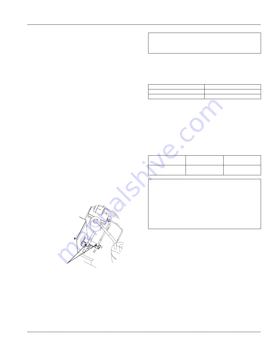
Step 5  Pressure Test and Evacuate Line Set and Ice 

Machine Head Section

•  Pressure testing and evacuation can be performed from 

the ice machine head section or CVD condensing unit 

shut-off valves.

•  Schrader valve core removal tools that allow for removal 

and installation of the valve cores without removing 

manifold gauge set hoses are recommended to decrease 

the evacuation time.

•  Pressure test @ 1000 kPa for a minimum of 15 minutes.
•  Minimum evacuation level is 500 microns.

Step 6  Leak Check the Refrigeration System

Leak check the new line set connections at the ice machine 

head section, condensing unit and S trap as well as all factory 

joints throughout the entire system. Disconnect power to the 

remote condensing unit. Place the rocker switch into the ON 

position. This allows the low side and high side pressures to 

equalize for leak checking. Place the rocker switch in the OFF 

position. Connect power to the remote condensing unit and 

allow system to pump down after leak checking is complete.

Step 7  Open the Valves Prior to Starting the Ice 

Machine

If the valves were not opened during the installation process, 

they must be opened before operating the ice machine.

A.  Backseat (open-turn counterclockwise) the suction 

line shutoff valve.

B.  Backseat (open-turn counterclockwise) the liquid 

line shutoff valve.

Verify suction and liquid line 

shut-off valves are open before 

operating the ice machine

Important

All refrigeration valve caps must be reinstalled to prevent 

future refrigeration leaks.

Verify O-ring in Schrader valve caps are intact and reinstall on 

shutoff valves to prevent refrigerant leakage. Replace shutoff 

valve access caps and torque to the following specifications.

Torque Values

Stem

24.4-27.1 Nm

Caps

16.3-20.3 Nm

Schrader Core

0.17-0.34 Nm

Step 8  Insulation Requirements

To prevent condensation, the entire suction line must be 

insulated. All insulation must be airtight and sealed at both 

ends.
The following insulation requirements prevent condensation 

at 32°C ambient 90% Relative Humidity. If higher humidity is 

expected, increase insulation thickness.
The entire suction line set requires:

Suction Line

Liquid Line

Min. Insulation 

Thickness

16 mm

10 mm

9 mm Suction Line  

9 mm Liquid Line

Important

To prevent condensation, the entire suction line must be 

insulated. All insulation must be airtight and sealed at 

both ends.
The minimum requirements are for conditions at or below 

90% humidity and 32°C ambient. When higher humidity 

will be experienced, or local code requires, insulation wall 

thickness will need to be increased.

Summary of Contents for Manitowoc RCUF1200

Page 1: ...umber 000016034 Rev 00 07 19 Flake and Nugget Model Ice Machines UFK UNK RFK RNK Installation Operation and Maintenance Manual Original Document Caution Read this instruction before operating this equ...

Page 2: ......

Page 3: ...perly trained technicians aware of the dangers of dealing with high voltage electricity and refrigerant under pressure The technician must also be certified in proper refrigerant handling and servicin...

Page 4: ...des and stability requirements Remove all removable panels before lifting and installing and use appropriate safety equipment during installation and servicing Two or more people are required to lift...

Page 5: ...e components obtained from the equipment manufacturers authorized replacement part network This equipment must be installed in accordance with the ASHRAE 15 Safety Standard for Refrigeration Systems T...

Page 6: ...f the appliance by a person responsible for their safety Do not allow children to play with clean or maintain this appliance without proper supervision n Warning Follow these precautions to prevent pe...

Page 7: ...h the authority having jurisdiction Turn off and lockout all utilities gas electric water according to approved practices during maintenance or servicing Units with two power cords must be plugged int...

Page 8: ...THIS PAGE INTENTIONALLY LEFT BLANK...

Page 9: ...nections 14 Cooling Tower Applications 14 Ice Machine Water Usage 14 Water Supply and Drain Line Sizing Connections 15 Electrical Service 16 Voltage 16 Fuse Circuit Breaker 16 Ground Fault Circuit Int...

Page 10: ...on 24 RN0620 RF0620 RN1100 RF1300 RF2500 RF1220 RF2200 Operation 24 Section 4 Maintenance Interior Cleaning and Sanitizing 25 Cleaning Sanitizing Procedure 25 Heavily Scaled Cleaning Procedure 25 Exte...

Page 11: ...RNK1100A RNP100A RNK100W RNF1020C RCUF1200 Flake Modular Models Self Contained Air Cooled Self Contained Water Cooled Rack Unit Head Section QuietQube Head Section RCU Remote Condensing Unit RFK0320A...

Page 12: ...quick and easy way to protect your investment Scan the QR code with your smart device or enter the link in a web browser to complete your warranty registration WWW MANITOWOCICE COM SERVICE WARRANTY WA...

Page 13: ...e ice machine and bin must be level Install the bin drain and ice machine drain separately Ice machine drain must be vented Bin drain termination must have an air gap When local code requires a backfl...

Page 14: ...r cooled condenser drain lines Insulate them to prevent condensation Vent the ice machine drain to the atmosphere The ice machine drain requires an 46 cm vent Do not vent the condenser drain on water...

Page 15: ...ater Inlet 3 32 C 138 1034 kPA 3 8 FPT RF2500 1 2 FPT Condenser Water Drain 1 2 MPT Bin Drain 3 4 FPT Large Capacity Bin Drain 1 FPT UNDERCOUNTER UNITS ROUTE DRAIN TUBING TO OPEN SITE DRAIN WATER SHUT...

Page 16: ...separate fuse circuit breaker are required for each ice machine GROUND FAULT CIRCUIT INTERRUPTER We do not recommend the use of a GFCI GFI circuit protection with our equipment If a GFCI GFI is requi...

Page 17: ...A N A UN0300 230 1 50 10 Amp N A 3 3 N A N A UF0388 230 1 50 10 Amp N A 3 3 N A N A UF0399 230 1 50 10 Amp N A 3 3 N A N A RF0320 230 1 50 20 Amp 12 8 N A N A N A RN0320 230 1 50 20 Amp 12 8 N A N A...

Page 18: ...0 0 145 RF2500 1 800 1 100 1 800 Condensers RJC0875 RJC1275 1 200 RJC2375 2 500 RJC4875 Data Is Not Currently Available Importan Manitowoc remote systems are only approved and warranted as a complete...

Page 19: ...ed personnel are required for proper rigging and lifting Step 1 Verify Ice Machine and Remote Condensing Unit Locations Are Within Guidelines Prior to installation of the ice machine head section and...

Page 20: ...he ice machine head section or the remote condensing unit Step 4 Connecting the line set To prevent oxidation of the copper purge line set and condensing unit with dry nitrogen while brazing A Connect...

Page 21: ...ned before operating the ice machine A Backseat open turn counterclockwise the suction line shutoff valve B Backseat open turn counterclockwise the liquid line shutoff valve Verify suction and liquid...

Page 22: ...ice making water turned on Are all electrical leads free from contact with refrigeration lines and moving equipment Has the owner operator been instructed regarding maintenance and the use of Manitow...

Page 23: ...3 6 RN0620 3 RF0620 3 RN1100 3 RFF1300 4 RF1220 3 RF2500 3 RF2200 3 1 2 3 4 5 6 7 1 2 3 4 5 6 7 BIN THERMOSTAT SMALL NUMBERS LESS ICE IN BIN LARGE NUMBERS MORE ICE IN BIN EVAPORATOR LOW TEMPERATURE SA...

Page 24: ...lb C The water reservoir is full of water Placing the toggle switch in the ON position starts the gear motor and a 10 minute compressor time delay The compressor starts and the float valve controls th...

Page 25: ...fter this procedure Exterior Cleaning Remove dust and dirt off exterior surfaces with mild household dishwashing detergent and warm water Wipe dry with a clean soft cloth Cleaning Sanitizing Procedure...

Page 26: ...witch opens Step 16 After all of the sanitizer water solution has been added to the reservoir turn on the ice making water supply Step 17 Continue the freeze cycle for 30 minutes and then discard all...

Page 27: ...brush or sponge NOT a wire brush to carefully clean the parts 5 Use the solution and a brush or sponge to clean all disassembled components and the inside of the bin 6 Rinse all cleaned parts with cle...

Page 28: ...and sanitize the ice machine 2 Press the power button and turn off the ice machine 3 Turn off the water supply disconnect and drain the incoming ice making water line at the rear of the ice machine an...

Page 29: ...n thermostat open or ice touching thermostat probe Adjust thermostat or remove ice No water in reservoir No water to ice machine plugged filter float valve defective Ice chute switch open Check for ic...

Page 30: ...30 Part Number 000016034 Rev 00 07 19 Troubleshooting Section 5 THIS PAGE INTENTIONALLY LEFT BLANK...

Page 31: ......

Page 32: ...s and premier chain operators or growing independents with industry leading equipment and solutions Our cutting edge designs and lean manufacturing tactics are powered by deep knowledge operator insig...

Reviews: