Weil-McLain GOLD SGO Manual Download Page 11

Place boiler

1.  Remove boiler from pallet.

  Do not drop boiler or bump jacket on 

floor or pallet. Damage to boiler can 

result.

  Smaller sized boilers may be top heavy.  

Use caution when handling to avoid 

minor personal injury or property dam-

age.

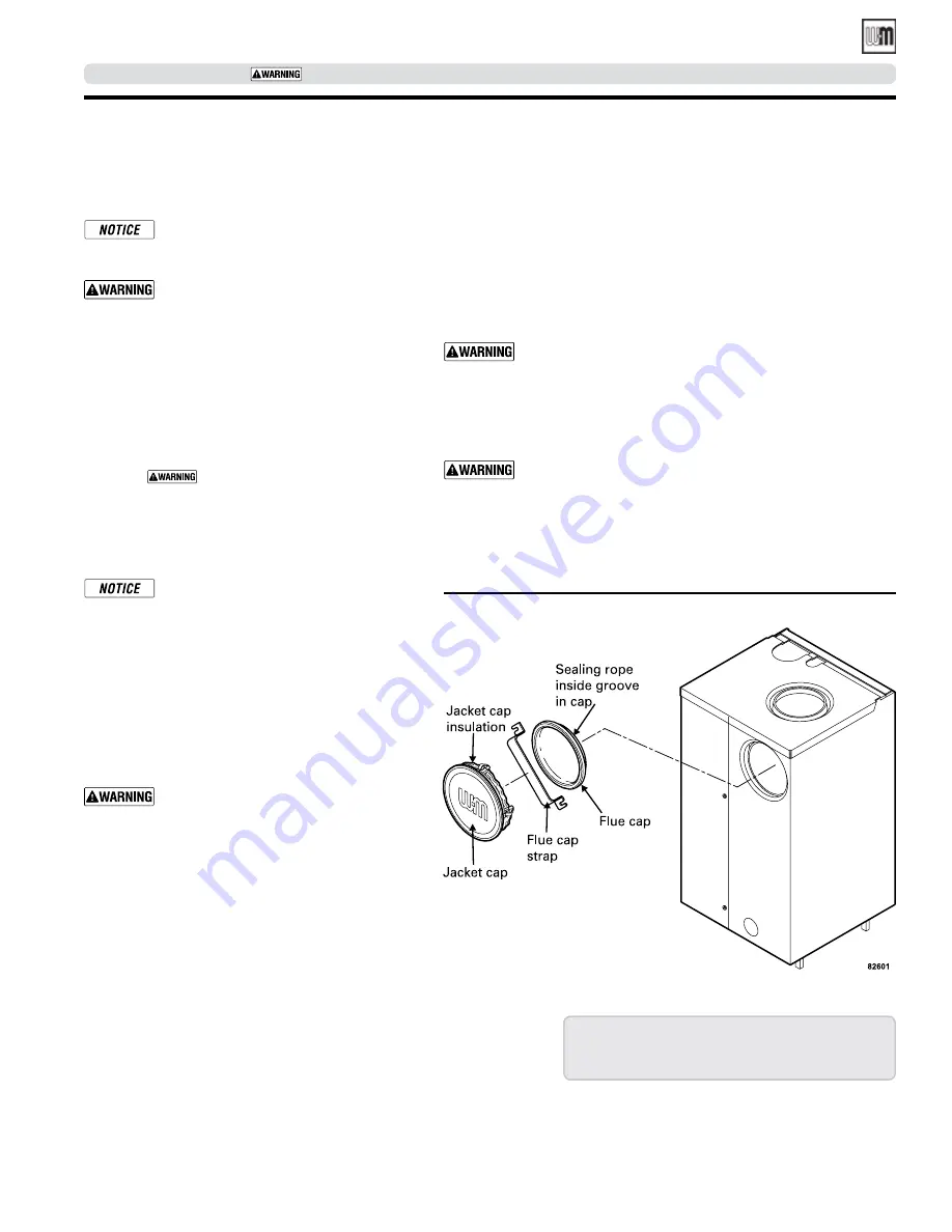
2.  Boiler is shipped for back flue outlet. To change to 

top flue outlet (see Figure 4):
a.   Remove jacket cap on top of boiler.
b.  Loosen two screws holding flue cap strap to 

collector hood. Remove strap and flue cap from 

opening. Re-tighten screws.

c.   Check rope placement inside flue cap.

 (Read 

 under step #5 below).

d.  Loosen two screws on back flue outlet. Set flue 

cap on outlet. Install strap by engaging slots 

in screws. Tighten screws. Make sure cap is 

securely installed.

e.  Snap jacket cap in back outlet opening.

  Jacket cap must be in place on boiler to 

avoid requiring an 18" minimum clear-

ance from back of boiler to combustible 

material.

3.  Check level. Shim legs, if needed.
4.  Check for secure placement of insulation on target 

wall, chamber floor and burner door.
5.  Visually check:
 

a. 

Flue collector hood seal.


b. 

Burner mounting door seal.

  Obtain gas-tight seal to prevent possible 

flue gas leakage and carbon monoxide 

emissions, which can lead to severe per-

sonal injury or death.

Tankless heater, if used

1.  Remove tankless heater knockout in left side of 

jacket panel and, for SGO-6 only, tankless heater 

control knockout.

2.  Remove tankless heater cover plate and gasket.
3.  Install new gasket and tankless heater over studs 

around opening. Secure with 3/8" nuts.

4.  Install tankless heater operating control where 

shown on page 23. If not furnished, use operating 

control with maximum 10°F differential.

Perform hydrostatic pressure test

1.  Remove steam pressure gauge furnished with boiler. Install water pres-

sure gauge for test only. Be sure gauge can handle test pressure.

2.  Install air vent in tapping on top of boiler.
3.  Remove pressure control and low water cutoff. Plug tappings.
4.  Plug supply and return tappings.
5.  Drain valve is already factory-installed.
6.  Fill boiler. Vent all air. Pressure test boiler at 45-55  psig.

  Do not leave boiler unattended. Cold water fill can expand 

and damage cast iron, resulting in severe personal injury, 

death or substantial property damage.

7.  Check for maintained gauge pressure for more than 10 minutes. Visu-

ally check for leaks if gauge pressure drops.

8.  Drain boiler. Repair leaks if found.

  Using petroleum-based compounds to repair leaks can dam-

age system components, resulting in property damage.

9.  Retest boiler after repairing leaks.
10. Remove pressure gauge, air vent and plugs. Re-install steam pressure 

gauge, pressure control and low water cutoff furnished with boiler.

Figure 4

  Change from back flue outlet to top flue outlet (optional)

Instructions for packaged boilers continued on  

page 16.

Install boiler — packaged boilers only

Part number 550-141-829/1211

11

GOLD 

SGO

 OIL-FIRED NATURAL DRAFT STEAM BOILER — SERIES 3 — 

Boiler Manual

SERVICE TECHNICIAN ONLY — read and follow completely.

Summary of Contents for GOLD SGO

Page 1: ......

Page 2: ...boiler rating label and CP number s from boiler jacket burner and controls On page 33 of this manual is space to list CP number s Packaged and non packaged boilers Packaged boilers available only in...

Page 3: ...nstall piping 18 To connect SGO boilers to indirect fired water heaters 18 Optional reservoir piping 21 Connect tankless heater piping 22 To pipe tankless heater 22 Connect tankless heater piping 23 C...

Page 4: ...ness consult local water treatment company When using antifreeze Use antifreeze especially made for hydronic systems Inhibited propylene glycol is recommended Do not use automotive ethylene glycol und...

Page 5: ...ately call service technician to repair Check float type low water cutoff when used Refer to control manufacturer s instructions Scald potential Do not blow down low water cutoff unless blow down pipi...

Page 6: ...press reset button on burner primary control only once Repeated presses will deposit oil in combustion chamber Burner must never be fired when oil is in combus tion chamber Immediately call qualified...

Page 7: ...e low water cutoff 1 If burner does not fire check for Service switch on boiler or additional switches turned off Fuses or breaker switch tripped Thermostat set below room temperature Fuel valves turn...

Page 8: ...ce technician pipe boiler exactly as shown in boiler manual Check valve inoperative Have qualified service technician clean or replace check valve Vacuum breaker inoperative Have qualified service tec...

Page 9: ...ence over jacket clearances Recommended SERVICE clearances 24 inches Front and top 6 inches Left side back and right side 15 inches Left side with tankless heater 12 inches Rightsideforburnerdoorswing...

Page 10: ...rectly or by ducts to the outdoors or to crawl or attic space that freely connects with outdoors Size per below Through outside wall or vertical ducts at least 35 sq in per 1 GPH input 1 sq in per 400...

Page 11: ...r cover plate and gasket 3 Install new gasket and tankless heater over studs around opening Secure with 3 8 nuts 4 Install tankless heater operating control where shown on page 23 If not furnished use...

Page 12: ...Metal to metal contact should be made around port openings If gap does exist it should be less than 020 Check with feeler gauge c If gap around port openings exceeds 020 check for dirt on port opening...

Page 13: ...lector hood Sealing rope with adhesive tape Nut Washer Tinnerman clip Screw Hold down lug Install boiler non packaged boilers only continued Separate block here for easier handling Part number 550 141...

Page 14: ...ails Install boiler controls See control tapping location Figure 6 control tappings Table 2 and Figure 7 or Figure 8 on page 15 to install controls 1 Do not use Teflon tape to install probe type low w...

Page 15: ...re 7 Steam boiler controls with float type LWCO optional tankless heater control Figure 8 Steam boiler controls with probe type LWCO optional tankless heater control Siphon SGO 3 to SGO 5 tankless hea...

Page 16: ...er to CSA B139 Installation Code for Oil Burning Equipment NFPA 211 requires chimney to be lined before con nected to boiler Inspect existing chimney before installing new boiler Failure to do any of...

Page 17: ...ottom of chimney to avoid blockage Breeching must not enter chimney far enough to cause obstruction Use thimble or slip joint where breeching enters chimney to allow removal for cleaning 4 When burner...

Page 18: ...Do not plug valve or place any obstruction in discharge line 3 Float type low water cutoff only install blowdown line in bottom of cutoff See Figure 11 or Figure 12 and also refer to low water cutoff...

Page 19: ...re 11 Steam piping for sizes 3 through 5 see Figure 12 page 20 for sizes 6 through 9 Part number 550 141 829 1211 19 GOLD SGOOIL FIRED NATURAL DRAFT STEAM BOILER SERIES 3 Boiler Manual SERVICE TECHNIC...

Page 20: ...through 9 see Figure 11 page 19 for sizes 3 through 5 Connect steam piping continued Part number 550 141 829 1211 20 GOLD SGOOIL FIRED NATURAL DRAFT STEAM BOILER SERIES 3 Boiler Manual SERVICE TECHNIC...

Page 21: ...eservoir piping Modern steam boilers are designed to steam for less time than older larger boilers When replacing an older steam boiler the system condensate return time may be longer than the steamin...

Page 22: ...ng Hot Water Can Scald Consumer Product Safety Commission and some states recommend domestic hot water temperature of 130 F or less When installing an automatic mixing valve selection and installation...

Page 23: ...ater pressure is limited to max 15 psig by approved steam relief valve Figure 14 Tankless heater piping SGO 3 5 tankless heater control location SGO 6 9 tankless heater control location Flow regulatin...

Page 24: ...d in flexible metal conduit Connect incoming line voltage HOT wire to service switch and neutral wire to white wire Field install equipment ground wire to green wire with wire nut Service switch 15 am...

Page 25: ...proceed as follows 1 Disconnect power 2 Install Spill Switch BVSS Wiring Harness P N 591 391 942 as follows a Remove cover from BVSS Box b Install straight fitting end of the harness on the BVSS Box...

Page 26: ...e 16 Boiler wiring for float type LWCO see Figure 18 page 27 for component locations Part number 550 141 829 1211 26 GOLD SGOOIL FIRED NATURAL DRAFT STEAM BOILER SERIES 3 Boiler Manual SERVICE TECHNIC...

Page 27: ...e yellow wires 4 Clip the quick connects from the blue wires coming from the BVSS Harness and strip 1 2 from the ends 5 Using two wire nuts from the kit wire the blue wires in series with the black an...

Page 28: ...e 19 Boiler wiring for probe type LWCO see Figure 20 page 29 for component locations Part number 550 141 829 1211 28 GOLD SGOOIL FIRED NATURAL DRAFT STEAM BOILER SERIES 3 Boiler Manual SERVICE TECHNIC...

Page 29: ...instructions 1 Locate and remove boiler junction box cover 2 Locate wire nut with two black wires if more than one exists pick the one with black wire going to the burner harness Clip the wire nut 3...

Page 30: ...se the tank settles Make swing joints so they will tighten as tank settles Non hardening pipe joint compounds should be used on all threads Do not use Teflon tape as an oil pipe sealant It can cause v...

Page 31: ...rve skim water level Raise waterline to midpoint of skim tapping Start up 2 Fire burner to maintain water temperature below steaming temperature during skimming process 3 Feed in water to maintain wat...

Page 32: ...ould re ignite when proper water level is restored Test additional field installed controls If boiler has additional operating control or other controls test for operation as outlined by control manuf...

Page 33: ...formed Above information is certified to be correct Information received and left with owner maintenance person Installation and service certificate Installer _________________________________________...

Page 34: ...ect and adjust burner See burner manual and change nozzle check ignition electrode settings clean blower housing and wheel make sure blower wheel turns freely oil burner motor if required clean air in...

Page 35: ...ueways and clean up between the sections to reach pins left uncleaned in step 5 7 Once the flueways are cleaned carefully remove the paper from the floor of the combustion chamber 8 Verify sealing rop...

Page 36: ...t adjust burner for a CO2 between 11 and 12 and 0 smoke b 0 01 to 0 02 W C draft in combustion chamber Controls requiring annual service Float type low water cutoff Follow instructions to blowdown cut...

Page 37: ...rately from other clothing Rinse clothes washer thor oughly NIOSH stated First Aid Eye Irrigate immediately Breathing Fresh air REMOVAL OF FIBERGLASS WOOL or INSTALLATION OF FIBERGLASS WOOL OR BASE PA...

Page 38: ...2 SGO 7 8 9 560 234 464 G Tie rod 1 2 x 10³ 4 SGO 7 560 234 491 Item Description Part No G Tie rod 1 2 x 121 4 SGO 3 560 234 493 G Tie rod 1 2 x 133 8 SGO 7 8 560 234 494 G Tie rod 1 2 x 14 SGO 8 9 56...

Page 39: ...factured parts will not be covered by warranty and may damage boiler or impair operation D J K J J C G G N Q E G F R B A P L J M H S Parts drawing Table 8 Series 3 section and flue collector parts Par...

Page 40: ...11B83 16 9 511 114 495 Low water cutoff float type McDonnell Miller 67W 2 10 511 100 007 Low water cutoff probe type Hydrolevel 45 469 1560 11 511 210 423 Drain cock 3 4 11 2 shank Conbraco 31 606 01...

Page 41: ...fic boiler as indicated in the list below Results from using modified or other manufactured parts will not be covered by warranty and may damage boiler or impair operation Part number 550 141 829 1211...

Page 42: ...81 355 521 381 355 596 381 355 531 381 355 532 426 700 258 381 355 533 Table 10 Boiler jacket Complete Jacket cartons UL Non UL 7 section 416 700 182 416 700 183 8 section 416 700 184 416 700 185 9 se...

Page 43: ...boiler as indicated in the list below Results from using modified or other manufactured parts will not be covered by warranty and may damage boiler or impair operation Part number 550 141 829 1211 43...

Page 44: ...77 8 R 7 DIA 177 8 299 16 750 9 Intermediate SGO side with burner Steam supply piping 3 9 Steam supply piping 6 9 73 16 182 6 41 16 103 2 14 Approx 7 DIA 177 8 A 7 DIA 177 8 151 2 393 7 L B Figure 26...

Page 45: ...221 8 587 2 SGO 6 19 482 6 231 2 584 2 261 4 666 7 SGO 7 221 8 561 8 261 8 663 4 293 8 746 2 SGO 8 251 4 641 4 29 742 9 321 2 825 5 SGO 9 283 8 720 9 323 8 822 4 355 8 904 7 Dimensions continued Part...

Page 46: ...only as an A unit 1 SGO boiler designed with convertible vertical and horizontal flue outlet 2 MBH refers to thousands of Btu per hour 3 Based on 140 000 Btu gal 4 Based on standard test procedures p...

Page 47: ...Notes Part number 550 141 829 1211 47 GOLD SGOOIL FIRED NATURAL DRAFT STEAM BOILER SERIES 3 Boiler Manual SERVICE TECHNICIAN ONLY read and follow completely...

Page 48: ...Part number 550 141 829 1211 GOLD SGOOIL FIRED NATURAL DRAFT STEAM BOILER SERIES 3 Boiler Manual...

Reviews: