Weil-McLain Gold Plus 40 User Manual Download Page 101

Part number 550-100-090/0809

101


gas

-

fired


water


boiler

 — 

Boiler Manual

MAINTENANCE & SPECIFICA

TIONS

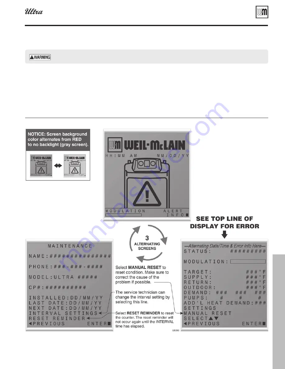
    U-Control display toggles when in lockout, with screen flashing red to gray

Figure 111

Troubleshooting


(continued)

U-Control fault indications

The U-Control provides diagnostic information for 

1. 

both automatic reset conditions and manual reset 

conditions. See Figure 104, page 90 for information 

available on the U-Control display.

2.  Figure  111  shows  the  screen  behavior  during  an 

automatic  or  manual  reset  condition.  The  table 

below the display illustration lists manual reset conditions and how 

to reset from them.

3.  Figure 112, page 102 lists conditions that will cause the control to dis-

play a constant red screen. The boiler will automatically restart if the 

condition self-corrects or the technician uses the U-Control’s manual 

reset screens to reset.

  Make sure to determine the causes of outages. Do not leave the boiler operating without a complete diagnosis.

Summary of Contents for Gold Plus 40

Page 1: ...l and all other information shipped with the boiler before installing Perform steps in the order given Failure to comply could result in severe personal injury death or substantial property damage Ins...

Page 2: ...ewall vent air termination Weil McLain cap 18 Install vent air piping boiler to W M termination 22 Install condensate line 23 Gas piping 25 Field wiring basic system 26 U Control operation and setup 2...

Page 3: ...ensate hose Install condensate pump and filter if required 25 Gas piping Verify gas pipe size Connect boiler to gas line 26 27 Field wiring Connect wiring to boiler and components 28 30 U Control oper...

Page 4: ...internal corrosion Leaks in boiler or piping must be repaired at once to prevent make up water Use this boiler ONLY in a closed loop system Do not add cold water to hot boiler Thermal shock can cause...

Page 5: ...in severe personal injury death or substantial property damage The Ultra boiler must be installed so that gas control system com 3 ponents are protected from dripping or spraying water or rain during...

Page 6: ...t the boiler so it cannot be damaged by a moving vehicle Ensure that the installation complies with all applicable codes Provide air openings to room Air openings Ultra boiler alone in boiler room No...

Page 7: ...n handle with care until the plastic components come to room temperature The Ultra boiler is generally easier to handle and maneuver after 1 removing from crate After removing outer shipping carton fr...

Page 8: ...with Figure 2 that would still allow bleeding air from shutoff valves Follow guidelines in this manual for piping components locations 9 and sizing Fill and pressure test Open the shutoff valves you...

Page 9: ...a 200 F external limit for example Separate low water cutoff A low water cutoff device is recommended when the boiler is in 1 stalled above piping level and may be required by certain state or local c...

Page 10: ...ron cast iron radiators or convectors DO NOT apply for radiant heating fan coil units or commercial installations Simplified pipe circulator selection Install the boiler and piping using the recommend...

Page 11: ...top of the air separator to remove residual air from the system Whenusingdiaphragmorbladdertanksonly whenthe boiler is installed above the system main piping install an automatic air vent in the top o...

Page 12: ...to the zone valves Also see the information on page 14 and page 15 for suggested piping and sizing Use at least the MINIMUM pipe size shown in Figure 5 on all boiler loop piping connecting boiler to...

Page 13: ...IMUM pipe size shown in Figure 6 on all boiler loop piping connecting boiler to and from the primary secondary connection item 21 Use only primary secondary piping as shown Failure to fol low these gu...

Page 14: ...GPM MBH 115 140 GPH 115 140 Head loss ft DHW pipe size CIRC PLUS model GPM MBH 115 140 GPH 115 140 Head loss ft DHW pipe size CIRC 80 71 MBH 40 6 5 71 71 160 124 8 5 1 007 40 6 5 71 71 160 124 8 5 1 0...

Page 15: ...er manual for piping 27 Automatic air vent must be installed in the vent tapping on top of the PLUS water heater Items supplied with boiler Items supplied by others 12 20 23 23 27 10 10 7 5 9 8 Zone v...

Page 16: ...ance When an existing boiler is replaced with an Ultra boiler the Ultra boiler CANNOT use the existing common vent The Ultra boiler requires its own vent and air piping as specified in this manual Th...

Page 17: ...re 11 page 16 and ensure the air intake will not be likely to draw in contaminated air Combustion air can be piped individually for each boiler or it can be 2 manifolded as shown in Figure 59 page 55...

Page 18: ...inch outside diameter pipe at the boiler vent and air connections Vent and air pipe minimum length Vent pipe and air pipe must each be at least 2 feet 1 long with 2 elbows if sidewall venting or 1 elb...

Page 19: ...connections at the boiler and the termination Allowable vent air pipe materials Use only the materials listed in 1 Figure 12 page 17 Maximum piping length Locate the termination such that the total ai...

Page 20: ...than 4 feet horizontally above or be c low from any electric meter gas meter regulator relief valve or other equipment Locate terminations so they are not likely to be damaged by foreign 4 objects su...

Page 21: ...h or substantial property damage Cut holes in the wall as shown in e Figure 21 using the location marks made with the template For best results use a small diameter long drill bit to drill centering h...

Page 22: ...inserted Wipe excess cement from joint Check joint to be f sure a smooth bead of cement shows around the entire joint Install pipe supports as shown in 10 Figure 22 page 21 Slope vent and air piping...

Page 23: ...wn in 8 Figure 25 Slide nipple through jacket condensate line hole to position as 9 shown in Figure 25 Cement the tee to the protruding nipple Be sure both nipple 10 and reducing elbow finish upright...

Page 24: ...low capacity When sizing condensate pumps make sure to include the total 4 load of all Ultra boilers connected to it The condensate line must remain unobstructed allow ing free flow of condensate If c...

Page 25: ...the correct outlet pressure This setting is suitable for natural gas and pro pane requiring no field adjustment Attempting to alter or measure the gas valve outlet pressure could result in damage to...

Page 26: ...20 VAC For circulators with higher amp ratings you must install a circulator relay or starter to provide line voltage to the circulator For circulators rated over 2 2 amps connect only the circula tor...

Page 27: ...own in piping diagrams on page 11 through page 15 Attach a sensor supplied with boiler to the system return pipe and wire to terminals P14 2 and 3 Locate sensor in the position shown in piping diagram...

Page 28: ...y and start priority timer If demand satisfied go to postpurge DHW heating Flame detected Release boiler to modulation immediately NOTE If flame is not detected the gas valve is turned off blower turn...

Page 29: ...ber 550 100 090 0809 29 gas fired water boiler Boiler Manual BASIC INSTALLATION U Control operation and setup continued U Control display and navigation Figure 34 see Figure 101 page 85 see Figure 101...

Page 30: ...tube baseboard with or without a DHW tank provided A DHW tank if used must be piped directly to the boiler as in the a piping shown in Figure 5 page 12 or Figure 6 page 13 If the DHW tank is a separat...

Page 31: ...d with Sentinel X100 inhibitor and 1 Sentinel inhibitor test kit See Repair Parts at the end of this manual for re ordering information After filling the system as directed in these instructions use 2...

Page 32: ...y After the system has been filled and leak tested verify water pH and 2 chlorine concentrations are acceptable Verify antifreeze concentration when used 3 Follow the instructions on the Sentinel test...

Page 33: ...while restricting flow in drain tube if boiler has been out of service for an extended period Failure to fill the trap could result in severe personal injury or death Final checks before starting boi...

Page 34: ...Check for gas tight seal at every connection and 1 seam of air piping and vent piping Startup final checks continued Venting system must be sealed gas tight to prevent flue gas spillage and carbon mon...

Page 35: ...090 0809 35 gas fired water boiler Boiler Manual BASIC INSTALLATION Startup final checks continued Operating instructions WARNING Verify that the U Control is set for the correct boiler model before p...

Page 36: ...on the venturi If throttle screw adjustment does not correct the problem then shut down the boiler and contact your local Weil McLain representative Throttle screw adjustment must be done only by a q...

Page 37: ...r that might indicate a need to check combustion 2 values at high fire as per page 36 to verify boiler is in adjustment include difficulty igniting poor flame stability at low fire combus tion noise o...

Page 38: ...r has a low water cutoff additional high limit or other controls tested for operation as outlined by manufacturer Boiler should be operating and should go off when controls are tested Verify controls...

Page 39: ...oilers This section provides application information and suggested piping for multiple boiler systems 62 76 Vent air piping alternatives This section provides installation instructions for four additi...

Page 40: ...de entering setting values and resetting after lockout 11 Flue pipe adapter with internal drain 12 Burner not shown Made with high grade stainless steel construction the burner uses pre mixed air and...

Page 41: ...Part number 550 100 090 0809 41 gas fired water boiler Boiler Manual ADVANCED INSTALLATION The Gas fired water boiler Featuring Flexibility...

Page 42: ...firing 13 Water outlet pipe system supply 14 Water return pipe system return 15 Gas connection pipe 16 U Control Module The U Control Module responds to signals from the room thermostats DHW aquastats...

Page 43: ...Part number 550 100 090 0809 43 gas fired water boiler Boiler Manual ADVANCED INSTALLATION The Gas fired water boiler Featuring Flexibility...

Page 44: ...altitude installations For installations more than 5 500 feet above sea level obtain the high altitude propane orifice kit Verify orifice size See Figure 41 Verify when installingthattheorificesizema...

Page 45: ...lve against venturi and replace 3 Allen head 10 screws securing valve to venturi Figure 42 page 44 or Fig ure 43 See 11 Figure 42 page 44 or Figure 43 Secure gas valve inlet adapter to gas valve with...

Page 46: ...of enclosure applies only for Ultra 80 through 230 Verify all parts listed above are available before proceeding g Stud spacing Bracket holes are spaced for studs on 16 inch centers 3 For other stud...

Page 47: ...ket and trace the outline of the screw slots with a 4 pencil Remove bracket and drill holes 1 4 diameter by 3 inches deep 5 centered on the screw slot outlines For metal stud walls using 3 16 toggle b...

Page 48: ...he piping as in Figure 48 The DHW water only flows through the secondary circuit connector piping NOTE Make sure to size the connector piping Figure 48 item 23 to handle the total flow it must handle...

Page 49: ...n Figure 49 on all boiler loop piping connecting boiler to and from the primary secondary connection item 21 Use only primary secondary piping as shown Failure to fol low these guidelines could result...

Page 50: ...heating applications The primary secondary piping shown ensures the boiler loop will have sufficient flow Size the system piping and circulator to provide the flow and pressure drop needed for the ra...

Page 51: ...from the primary secondary connection item 21 Use only primary secondary piping as shown Failure to fol low these guidelines could result in system problems Thespaceheatingsystemmaybezonedwithcircula...

Page 52: ...rop H1 and the pressure drop in the piping H2 Make sure to use the cop per pipe size given in column 3 when piping the water heater Step 4 Add the pressure drop across the water heater from Step 1 to...

Page 53: ...6 6 2 7 9 16 1 11 6 4 2 10 14 1 14 6 2 5 Ultra 105 94 000 Btuh output 7 27 1 7 0 2 7 9 21 1 11 2 4 2 10 19 1 13 6 2 5 13 14 1 22 2 3 9 Ultra 155 139 000 Btuh output 9 31 1 6 2 2 1 10 0 28 1 7 7 2 5 1...

Page 54: ...or boiler 4 room floor Uncrate assemble and mount boilers according to 5 instructions in this manual Provide clearance for installation of venting air 6 piping gas piping expansion tank primary circu...

Page 55: ...ter damper has opened ONLY air piping can be combined DO NOT use combined vent piping Flue gas leakage and boiler component damage can occur Failure to comply could result in severe personal injury de...

Page 56: ...boiler as shown Some local codes may require the use of individual water level controls and limits on each boiler when isolation valves are installed Install main system air eliminator and primary cir...

Page 57: ...ucing valve 11 Check valve or backflow preventer as required by applicable codes 12 Isolation valve 13 Cold water supply 14 Supply water temperature control when used 15 Low water cutoff when used pla...

Page 58: ...eturn 20 Boiler relief valve and discharge piping installed per Ultra Boiler Manual 21 Indirect fired storage water heaters Weil McLain PLUS Line shown Example is shown connected to one boiler of the...

Page 59: ...outlet 24 DHW boiler side circulators 25 DHW boiler side supply Easy Fit Manifold 26 DHW boiler side return Easy Fit Manifold 27 Flow check valves to prevent induced or gravity flow in heating system...

Page 60: ...rom boiler connection tees Notes 1 Contact heat exchanger manufacturer for heat exchanger shell side and tube side piping and circulator require ments Tube side flow and temperatures must meet heating...

Page 61: ...ly in line with the exhaust vent terminal for the horizontally vented gas fueled heating appliance or equipment The sign shall read in print size no less than one half 1 2 inch in size GAS VENT DIRECT...

Page 62: ...lent length of piping 7 feet per for each 4 inch elbow 2 or 3 inch 90 long radius or 45 elbow 16 feet for each 2 or 3 inch short radius elbow a Use 3 x2 reducer at boiler b Use 3 x2 PVC reducers at te...

Page 63: ...which will cause the air pipe to be slightly higher or lower than the vent but the center lines will match those at the boiler vent and air connections Determine locations for terminations A gas vent...

Page 64: ...e any public walkway At least 3 feet above any forced air intake within 10 feet No closer than 12 inches below or horizontally from any door or window or any other gravity air inlet Air inlet must ter...

Page 65: ...3 The vent and air piping must be securely supported and must not rest its weight on the boiler fittings Failure to properly support the vent and air piping could result in vent piping damage resultin...

Page 66: ...es and lengths must be maintained Space braces no further than 24 inches apart See WARNING below for extremely cold climates External venting greater than 4 feet requires an insulated enclo d sure aro...

Page 67: ...ge to exterior g finishes Maintain clearances as shown in the illustrations in this manual 5 section Also maintain the following Vent must terminate a At least 6 feet from adjacent walls No closer tha...

Page 68: ...4 through floors or walls Seal exterior openings thoroughly with exterior caulk 5 Termination and fittings Prepare the vent termination elbow and the air termination el 1 bow Figure 80 by inserting bi...

Page 69: ...where the plume could obstruct window views Prevailing winds could cause freezing of condensate and water c ice buildup where flue products impinge on building surfaces or plants Avoid possibility of...

Page 70: ...2 Installation Code The air inlet of an Ultra boiler is part of a direct vent connection 4 It is not classified as a forced air intake with regard to spacing from adjacent boiler vents Prepare roof p...

Page 71: ...tical vent air termination 3 PVC concentric continued Weil McLain 3 PVC concentric termination assembly Figure 85 Weil McLain 3 PVC concentric termination Figure 84 assembly DO NOT attach the rain cap...

Page 72: ...personal injury death or substantial property damage When inserting the partially assembled termination kit through the roof penetration wrap plastic or other protection over the end of the exposed as...

Page 73: ...er the surroundings when terminating the vent 4 and air Position the vent termination where vapors will not damage a nearby shrubs plants or air conditioning equipment or be objectionable The flue pro...

Page 74: ...nt termination elbow and the air termination elbow 1 Figure 89 page 73 by inserting bird screens Bird screens must be purchased separately See the parts list at the end of this manual for part numbers...

Page 75: ...ing turn e Make sure pipe is fully inserted Wipe excess cement from joint Check joint to be sure a smooth f bead of cement shows around the entire joint Install pipe supports as shown in 10 Figure 92...

Page 76: ...runs Install a hanger support within 6 inches of any upturn in the piping Support vertical runs on the outside of the building with brackets as shown in the termination instructions Slope horizontal...

Page 77: ...supplier to size pipes tanks and 100 lockup gas pressure 1 regulator Propane supply pressure Adjust propane supply regulator provided by gas supplier for 13 w c 1 maximum pressure Pressure required a...

Page 78: ...ect piping to the boiler with Circulator 1 being the only circulator being activated Wiring general The U Control provides plug in color coded non interchangeable 1 terminal strips for all field wirin...

Page 79: ...If connected directly to the boiler set anticipator for 0 1 amps If connected to relays or other devices set to match total elec trical power requirements of connected devices See device manufacturers...

Page 80: ...Part number 550 100 090 0809 gas fired water boiler Boiler Manual 80 Field wiring advanced see Figure 98 Figure 99 continued Figure 98 Schematic wiring diagram Ultra 80 through Ultra 299...

Page 81: ...t number 550 100 090 0809 81 gas fired water boiler Boiler Manual ADVANCED INSTALLATION Figure 99 Ladder wiring diagram Ultra 80 through Ultra 299 Field wiring advanced see Figure 98 Figure 99 continu...

Page 82: ...7 Connect these terminals to call for heat from the other heat source 2 See the following section to program the boiler to activate the other source either as the primary or secondary heat source Alar...

Page 83: ...outdoor sensor tem 1 perature to account for solar or other effects that would cause the sensor to read incorrectly ADDITIONAL HEAT DEMAND This setting is for multiple boilers or multiple heat 1 ing s...

Page 84: ...d 3 usually used for space heating circuits Each of the three inputs has its own set of 3 operating parameters programmed using the menus shown in Figure 102 page 86 The inputs to the U Control are 4...

Page 85: ...eeper system RADFLOOR RAF 140 0 90 70 Custom CUSTOM CUS 190 0 70 70 Does not pass along Add l Heat Demand DHW system DOMESTIC DHW 190 DHW heating ignores outdoor reset and warm weather shutdown U Cont...

Page 86: ...COIL FINNED TUBE BASEBOARD CAST IRON BASEBOARD CAST IRON RADIATOR RADIANT SLAB ON GRADE RADIANT THIN SLAB RADIANT ABOVE FLOOR CUSTOM DHW DIRECT DHW SYSTEM TEMPERATURES MAX SUPPLY F MIN SUPPLY F MAX O...

Page 87: ...ULATOR 3 BLOWER SIGNAL ADD L HEAT DEMAND ALARM ANALOG OUT ERRORS CONTROL FAULT IGNITION RETRIES MANUAL RESET CNT AUTO RESET CNT LOCKOUT HISTORY 1 LOCKOUT HISTORY HH MM AM MM DD YY STATUS MANUAL RESET...

Page 88: ...t Modulate On Diff F 2 10 5 Boiler turns on if temperature drops below target minus differential on Modulate Off Diff F 2 10 5 Boiler shuts down if modulates past target plus differential off Max On T...

Page 89: ...get temperature Modulate On Diff F 2 10 5 Boiler turns on if temperature drops below target minus differential on Modulate Off Diff F 2 10 5 Boiler shuts down if modulates past target plus differentia...

Page 90: ...water cutoff device on P12 3 P12 4 Blower Tach rpm data Feedback from blower sensor Flame Signal no units data Number indicating the presence and quality of the flame used to shutdown boiler Outputs G...

Page 91: ...ition Name of the system Type being satisfied post purge Warm Weather Shutdown Trouble Target F data Calculated target temperature based on outdoor temp or the max setpoint if no ODR Modulation F data...

Page 92: ...me inspection stable uniform Flame signal see Figure 106 page 96 Clean heat exchanger if flue temp is more than 54 F above return water temp Inspect jacket front door gaskets replace if necessary Addi...

Page 93: ...and ignitor gasket See listing in Re placement parts section of this manual These parts must be on hand when you perform the first year inspection in the event they must be replaced Failure to replac...

Page 94: ...maged resulting in unreliable or unsafe operation Clean condensate trap Loosen condensate trap line hose clamps and remove trap 1 line Empty water from trap line and inspect Flush out if needed 2 with...

Page 95: ...uently the expansion tank may 2 be waterlogged or undersized Closed type tank tank is most likely waterlogged Install a tank fitting if not already installed Then check fill level per fitting manufact...

Page 96: ...rews bend up the retainer tabs as shown in Figure 107 to prevent screw rotation Reattach the cover plate using the method given in 5 Figure 113 page 110 or Figure 115 page 111 After servicing reinstal...

Page 97: ...ges listed in the previous 10 steps contact the factory for technical assistance Check flue gas temperature Set the boiler to high fire Then adjust the U Control mod 1 ule display to view flue gas tem...

Page 98: ...al property damage Following installation the valve lever must be operated AT LEAST ONCE A YEAR to ensure that waterways are clear Certain naturally occurring mineral deposits may adhere to the valve...

Page 99: ...ontrols Wiring errors can cause improper and dan gerous operation Always disconnect power to boiler before servicing Failure to comply could result in severe personal injury death or substantial prope...

Page 100: ...not jumper fuse or replace with any fuse except as specified Failure to comply could result in severe personal injury death or substantial property damage Reinstall jacket top panel and boiler jacket...

Page 101: ...information available on the U Control display 2 Figure 111 shows the screen behavior during an automatic or manual reset condition The table below the display illustration lists manual reset conditio...

Page 102: ...t this count Ignition Retries Displays the number of ignition attempts in the current ignition sequence Manual Reset Count Records number of lockouts that required a manual reset since this count was...

Page 103: ...supply water temperature in heat exchanger rises faster than 2 F per second during the first two minutes the burner is on Automatically resets after 1 minute delay or using manual reset on display Man...

Page 104: ...rature and system water temperature sensors If these are not being used they will always be shown as OPEN This is normal unless the sensors were installed Check wire harness for loose connections and...

Page 105: ...operly Each Priority input can be configured to turn on any combination of three circulator outputs Refer to the U Control Setup section to configure these properly for the system Verify water pipe is...

Page 106: ...condensate trap for blockage allowing condensate to accumulate inside heat exchanger Fouled worn bent or faulty igniter Fouled igniters can be cleaned for additional use with fine grit sand paper or s...

Page 107: ...use gas pressure switches Requires manual reset Check boiler size selected in U Control against boiler rating label Correct if necessary to select the proper boiler size HW FAULT EXPANSION BRD Expans...

Page 108: ...f yes description Auto reset Auto reset Auto reset If yes description If yes description If yes description Priority 1 Priority 1 Priority 1 Priority 2 Priority 2 Priority 2 Priority 3 Priority 3 Prio...

Page 109: ...om the aluminum The oxide layer will reform but if small amounts of the trisodium phosphate remain in the system the chemical will continue to remove the protective oxide layer leading to reduced heat...

Page 110: ...long to loosen deposits See Figure 114 See water spraying notice on next page Inspect the heat exchanger cover plate insulation Replace if insu 9 lation is damaged Read the ceramic fiber WARNING on pa...

Page 111: ...ce cover plate Reinstall hex head nuts on the cover plate mounting studs and 13 tighten in a staggering pattern until cover plate is uniformly tightened You must gradually tighten the cover plate nuts...

Page 112: ...ry or death Propane conversion kits and instructions Figure 116 The conversion kits listed below are only for use with Ultra Series 3 boilers For series 1 or series 2 boilers refer to the boiler manua...

Page 113: ...5 plate gasket cover plate insulation burner gasket Ultra 155 399 flue sensor gasket and venturi gasket 383 500 605 383 500 620 7 Pressure relief valve ASME 30 PSI 3 4 NPT male Ultra 80 299 Ultra 80 3...

Page 114: ...oor 2 required All 383 500 320 4 Knurled head screw clip on receptacle not shown 2 required All 383 500 180 5 Air adapter kit Includes adapter 3 gasket and mounting bracket 3 4 80 105 155 230 399 383...

Page 115: ...oor temperature sensor 510 312 218 9 Display to U Control wire harness not shown 383 500 633 10 Upper line voltage wire harness male not shown 383 500 634 11 Lower line voltage wire harness female not...

Page 116: ...drain valve 3 4 NPT All 511 246 392 15 Blower assembly kit Blower gasket and hardware 80 105 383 501 027 16 Gas pipe 80 105 560 907 682 17 Flexible gas line section and shut off valve 80 105 383 500 6...

Page 117: ...090 0809 117 gas fired water boiler Boiler Manual MAINTENANCE SPECIFICATIONS Heat exchanger and piping Ultra 80 and 105 Figure 121 Replacement parts continued Go to www weil mclain com to locate Weil...

Page 118: ...230 383 500 280 13 Return water pipe assembly Pipe drain valve cap assembled compression fitting 155 230 383 500 285 16 Boiler drain valve 3 4 NPT All 511 246 392 17 Blower assembly kit Blower gasket...

Page 119: ...6 Boiler drain valve 3 4 NPT All 511 246 392 17 Blower assembly kit Blower gasket and hardware 299 399 383 500 360 383 500 650 18 Gas pipe 299 399 560 907 679 19 Flexible gas line section and shut off...

Page 120: ...uted through bottom of enclosure using wall mounting kit See page 5 for mounting instructions 2 Boiler circulator is shipped loose Circulator must be mounted in the return piping Both 1 and 1 circulat...

Page 121: ...iler firing rate will affect AFUE rating 2 Based on standard test procedures prescribed by the United States Department of Energy 3 Net I B R ratings are based on net installed radiation of sufficient...

Page 122: ...23 56 48 3 315 282 8 4 245 157 3 465 417 12 5 363 232 3 690 621 18 6 540 345 3 897 810 24 2 702 449 3 1197 1095 32 7 951 578 4 320 284 8 5 247 160 114 24 56 49 4 420 376 11 2 327 210 4 620 556 16 6 48...

Page 123: ...l McLain Technical Services for other allowances 3 Foundation sizes in Figure 126 provide 6 inches between boilers and 2 inches from boiler to edge of foundation Smaller foundations are possible with...

Page 124: ...Type System Type System Type Max Supply F Max Supply F Max Supply F Min Supply F Min Supply F Min Supply F Max OD Reset F Max OD Reset F Max OD Reset F Min OD Reset F Min OD Reset F Min OD Reset F Mod...

Reviews: