


Part number 550-100-305/0118
103
AquaBalance
TM
W
ALL
M
OUNT
GAS
-
FIRED
WATER
BOILER
—
Boiler Manual
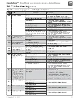
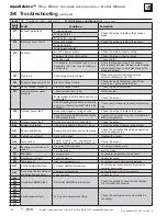
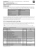
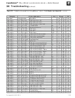
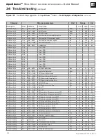
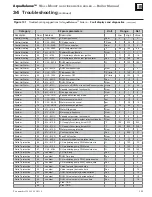
Category
E2 prom parameters
Unit
Range
Def
Description Num.
Address
Description
Low
High
Value
Central Heating
53
CL5 – 059D
CH pump selection
Num
0
7
0
Central Heating
54
CL5 – 0592
CH slope control
°F/min
1
20
11
Central Heating
55
CL5 – 055E
OTC curve selection
Num
0
10
0
Central Heating
56
CL5 – 0562
OTC temperature offset
°F
68
104
86
Central Heating
58
ML – 811A
Summer/Winter function
Num
0
1
1
Central Heating
59
ML – 8129
CH hysteresys after burner ignition
°F
11
54
18
Central Heating
60
ML – 8120
CH hysteresys after burner ignition timer
Sec
60
180
60
Dom. Hot Water
61
CL5 – 06F8
DHW maximum output
%
0
100
100
Dom. Hot Water
62
Free - TBD
Dom. Hot Water
63
ML – 80D9
$;#X]#^X
Num
0
1
0
Dom. Hot Water
64
CL5 – 127A
Flow sensor ON
QZ\]
0
100
15
Dom. Hot Water
65
CL5 – 1285
Flow sensor OFF
QZ\]
0
100
10
Dom. Hot Water
66
ML – 80DE
$;#X]#{Q^X
Sec
0
10
0
Dom. Hot Water
67
ML – 811F
DHW Off mode
Num
0
4
0
Dom. Hot Water
68
ML – 813C
`#]$;^#X^^jX]ZZX
Hours
0
24
24
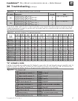
System
69
ML – 8122
Variable input switch functionality
Num
0
4
4
System
70
ML – 8123
Gas type selection
Num
0
1
0
System
71
CL5 – 121C
Fan speed in Stand-by mode
Hz
0
70
0
System
72
CL5 – 0934
Water pressure low limit
psi
0
12
6
System
73
CL5 – 0A38
Water pressure nominal
psi
7
29
10
System
74
CL5 – 2EDF
Water pressure high limit
psi
36
50
41
System
75
ML – 8128
"^X{QQ\]!ZX
Num
0
1
0
System
76
ML – 811B
Main supply frequency
Num
0
1
1
System
77
ML – 80DC
Variable output relay functionality
Num
0
8
0
System
78
ML – 812A
External pcb variable output relay functionality
Num
0
8
7
System
79
ML – 812B
CH supply2 over-temp_burnerOFF
°F
194
230
230
System
80
ML – 812C
CH supply2 over-temp_burnerON
°F
194
230
226
System
81
ML – 812D
Water pressure protection
Num
0
1
0
System
82
ML – 813B
Post-Ventilation time
Sec
0
255
27
System
83
ML – 813D
Fault F20 function
Num
0
1
0
System
84
ML – 80E0
3-way motor valve commutation timer
Sec
4
10
4
Delta T protection
85
ML – 812E
CH modulating pump PWM absolute min
%
0
100
30
Delta T protection
86
ML – 812F
CH modulating pump PWM start
%
0
100
75
Delta T protection
87
CL5 - 0C64
CH modulating pump PWM absolute max
%
0
100
100
Delta T protection
88
constant
CH Time loop
Sec
2
Delta T protection
89
constant
DHW Time loop
Sec
2
Delta T protection
90
constant
CH modulating pump PWM_decrease step
%
1
Delta T protection
91
constant
CH modulating pump PWM_update_time
Sec
4
Delta T protection
92
constant
Virtual set point_decrease step
°F
4
Delta T protection
93
constant
Virtual set point_decrease time
Sec
10
Delta T protection
94
constant
DHW Virtual set point_decrease time2
Sec
12
Delta T protection
95
constant
DHW Virtual set point_decrease time1
Sec
18
Delta T protection
96
constant
DHW Virtual set point_increase time
Sec
18
97
Free
-
TBD
98
Free
-
TBD
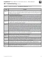
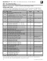
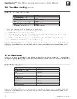
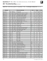
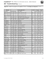
Figure 131
Troubleshooting suggestions for
AquaBalance
™
boilers —
Fault displays and diagnostics
(continued)
34
Troubleshooting
(continued)