8�2
Connection
Î
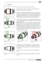
Grip the connector by its grip sleeve (Pos. 1).
Î
Pull the grip sleeve (Pos. 1) of the connector backwards
). The connector is opened.
Î
Hold the connector by the lower part (Pos. 2) and the grip
sleeve (Pos. 1) pulled back. Press the hose into the connec-
tor until the clamping jaws (Pos. 3) snap together (
Attention:
There is a slight pre-compression on the hose.
Pressing the hose onto the connector can be difficult.
Î
Push the grip sleeve (Pos. 1) forward by hand until it is flush
with the clamping jaws (Pos. 3) (
). The connector is
now connected.
Note:
If your connector is equipped with an integrated shut-
off valve, this is pressed open by connecting the connector.
Attention:
If the outer edges of the external diameter of
the clamping jaws are visible (
and
) or the
retaining ring is not visible, then the connector is not cor-
rectly connected. The connector may spring out of place
and medium may escape.
Î
Pull gently on the lower part (Pos. 2) of the connector
(red arrow
) in the direction opposite that of the
connection to make sure that the connector is properly
connected.
- The connector is now connected pressure-tight to the
hose.
Î
To start the testing procedure, apply pressure to media
inlet ‘B1’.
Figure 3
Figure 2
Figure 5
Figure 6
Figure 4
Figure 7
pull backwards
MD-10235-L51-R1.0.0-03
Page 17
Operating instructions
AE


