11371757 Installation, operation and maintenance manual – Squirrel cage motor – M line – Vertical
l 25
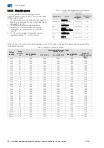
4.5.1.3
Temperature and ohmic resistance of the PT100 thermoresistance
Table 4.6 shows the temperature as a function of the ohmic resistance measured across PT100 RTDs.
Table 4.6: Temperature X Resistance (Pt100)
º C
0
1
2
3
4
5
6
7
8
9
0
100.00
100.39
100.78
101.17
101.56
101.95
102.34
102.73
103.12
103.51
10
103.90
104.29
104.68
105.07
105.46
105.95
106.24
106.63
107.02
107.40
20
107.79
108.18
108.57
108.96
109.35
109.73
110.12
110.51
110.90
111.28
30
111.67
112.06
112.45
112.83
113.22
113.61
113.99
114.38
114.77
115.15
40
115.54
115.93
116.31
116.70
117.08
117.47
117.85
118.24
118.62
119.01
50
119.40
119.78
120.16
120.55
120.93
121.32
121.70
122.09
122.47
122.86
60
123.24
123.62
124.01
124.39
124.77
125.16
125.54
125.92
126.31
126.69
70
127.07
127.45
127.84
128.22
128.60
128.98
129.37
129.75
130.13
130.51
80
130.89
131.27
131.66
132.04
132.42
132.80
133.18
133.56
133.94
134.32
90
134.70
135.08
135.46
135.84
136.22
136.60
136.98
137.36
137.74
138.12
100
138.50
138.88
139.26
139.64
140.02
140.39
140.77
141.15
141.53
141.91
110
142.29
142.66
143.04
143.42
143.80
144.17
144.55
144.93
145.31
145.68
120
146.06
146.44
146.81
147.19
147.57
147.94
148.32
148.70
149.07
149.45
130
149.82
150.20
150.57
150.95
151.33
151.70
152.08
152.45
152.83
153.20
140
153.58
153.95
154.32
154.70
155.07
155.45
155.82
156.19
156.57
156.94
150
157.31
157.69
158.06
158.43
158.81
159.18
159.55
159.93
160.30
160.67
4.5.1.4
Space heater
When the motor is equipped with a space heater to
prevent internal water condensation during long periods
out of operation, it must be assured that the space heater
is energized shortly after turning the motor off, and that it
is de-energized before the motor is put into operation.
The values of the space heater supply voltage and power
are informed in the connection diagram and in the specific
plate affixed to the motor.
4.5.2
Water leak sensor
Motors with air-water heat exchangers are supplied with a
water leak sensor intended to detect accidental water
leaks from the radiator into the motor. This sensor must
be connected to the control panel, according to the motor
connection diagram. The signal of this sensor must be
used to activate the alarm.
When this protection actuates, the heat exchanger must
be inspected and, if any water leak is detected, the motor
must be shut down and the problem corrected.
4.6
COOLING
The motor cooling system type may vary according to its
application.
Only the correct installation of the motor and of the cooling
system can ensure its continuous operation without
overheating.
ATTENTION
The protection devices of the cooling system
(if any) must be monitored periodically.
The air and/or water inlets and outlets (if any)
must not be obstructed, because this could
cause overheating and even lead to the
motor burnout. For further details, refer to the
motor dimensional drawing.
4.6.1
Air-water heat exchange cooling
In motors with air-water heat exchanger, the internal air, in
a closed circuit, is cooled by the radiator, which is a
surface heat transmitter designed to dissipate heat.
Clean water with the following characteristics must be
used as coolant:
pH: 6 to 9;
Chlorides: maximum 25.0 mg/l;
Sulphates: maximum 3.0 mg/l;
Manganese: maximum 0.5 mg/l;
Suspended solids: maximum 30.0 mg/l;
Ammonia: without ammonia dashes.
ATTENTION
Data of the radiators that compose the air-
water heat exchanger are informed on their
nameplate and on the motor dimensional
drawing.
This data must be observed for the proper
operation of the motor cooling system, thus
preventing overheating.
4.6.1.1
Radiators for application with seawater
ATTENTION
Formula:
Ω
- 100 =
°
C
0.386

