background image

www.weg.net

Manual de instrucciones para montaje y mantenimiento de seccionadoras fusibles

17

CONTENIDO

ESPAÑOL

1. OPERACIONES BÁSICAS 

18

1.1. APERTURA DE LA TAPA .................................................................. 18

1.2. CIERRE DE LA TAPA ........................................................................ 18

1.3. RETIRADA DE LA TAPA ................................................................... 18

1.4. MONTAJE DE LA TAPA .................................................................... 19

1.5. RETIRADA DE LA PROTECCIÓN DE TERMINALES ..................... 19

1.6. MONTAJE DE LA PROTECCIÓN DE TERMINALES ...................... 20

2. MONTAJE DE LA SECCIONADORA 

20

2.1. MONTAJE DE LA SECCIONADORA EN LA BASE DE MONTAJE .... 20

3. FIJACIÓN DE LOS CONDUCTORES DE SALIDA 

21

3.1.  FIJACIÓN DE LOS CONDUCTORES CON TERMINAL DE CABLE - 

GRAPA TORNILLO TIPO M ................................................................21

3.2.  MONTAJE DE CONDUCTORES CON TERMINAL DESNUDO - 

GRAPA PUENTE TIPO S .................................................................... 21

4.  INSERCIÓN, RETIRADA Y VERIFICACIÓN DE LAS  

CONDICIONES DE LOS ESLABONES FUSIBLES 

22

4.1. INSERCIÓN DE LOS ESLABONES FUSIBLES ............................... 22

4.2. RETIRADA DE LOS ESLABONES FUSIBLES ................................ 22

4.3.  VERIFICACIÓN DE LAS CONDICIONES DE LOS  

ESLABONES FUSIBLES .................................................................. 23

5. BLOQUE DE CONTACTO AUXILIAR.......................................................23
6. DESCARTE DEL MATERIAL UTILIZADO............................................... 23
7. CONDICIONES DE TRANSPORTE Y ALMACENAMIENTO................... 23

Summary of Contents for FSW 630

Page 1: ...n Energy Transmission Distribution Coatings Manual de instru es para a montagem e manuten o de seccionadoras tipo fus vel Manual de instrucciones para montaje y mantenimiento de seccionadoras fusibles...

Page 2: ...vel 2 17 23 Manual de instrucciones para el montaje y mantenimiento de seccionadores tipo fusible Espa ol 3 9 Manual de instru es para a montagem e manuten o de seccionadoras tipo fus vel Portugu s 1...

Page 3: ...A SECCIONADORA 6 2 1 MONTAGEM DA SECCIONADORA NA BASE DE MONTAGEM 6 3 FIXA O DOS CONDUTORES DE SA DA 7 3 1 FIXA O DOS CONDUTORES COM TERMINAL DE CABO GRAMPO PARAFUSO TIPO M 7 3 2 MONTAGEM DE CONDUTORE...

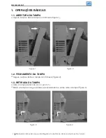
Page 4: ...ABERTURA DA TAMPA Segure a al a e abra a tampa com firmeza Figura 1 Figura 2 Figura 1 1 2 FECHAMENTO DA TAMPA Segure a al a e feche a tampa com firmeza Figura 2 1 3 RETIRADA DA TAMPA Abra a tampa de a...

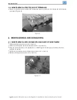
Page 5: ...e ent o mova a tampa ao longo da base da seccionadora e feche com firmeza 4 1 5 RETIRADA DA PROTE O DE TERMINAIS Gire o parafuso 90 graus na prote o de terminais selecionada Figura 5 e Figura 6 Figur...

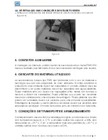
Page 6: ...rminais se prendam Figura 9 Figura 9 2 MONTAGEM DA SECCIONADORA 2 1 MONTAGEM DA SECCIONADORA NA BASE DE MONTAGEM Retire a tampa de acordo com o item 3 Retire as prote es de terminais de acordo com ite...

Page 7: ...dutores com parafuso M12 com torque de 20 Nm Figura 11 Figura 11 O kit de parafusos composto por 12 parafusos M8 e 6 grampos tipo S Ficando a crit rio do cliente a utiliza o de parafusos M12 3 2 MONTA...

Page 8: ...com o item 3 Coloque o elo fus vel em um porta fus vel Figura 13 mova o elo fus vel ao longo da tampa at a trava de elos fus veis prender Monte a tampa de acordo com o ponto 4 Figura 13 4 2 RETIRADA D...

Page 9: ...to utilizado deve ser desmontado e as pe as met licas devem ser separadas das pe as pl sticas Pe as met licas sem uso devem ser segregadas entre metais n o ferrosos e ferrosos e devem ser sucateadas P...

Page 10: ...DISCONNECTOR 13 2 1 MOUNTING THE DISCONNECTOR ON THE MOUNTING PLATE 13 3 FIXING OUTGOING CONDUCTORS 14 3 1 FIXING CONDUCTORS WITH CABLE TERMINAL M TYPE BOLT CLAMP 14 3 2 MOUNTING OF CONDUCTORS WITH BA...

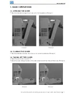
Page 11: ...e handle and open the cover up to firm resistance Picture 1 Picture 1 Picture 2 1 2 CLOSING THE COVER Take the handle and close the cover up to confirm resistance Picture 2 1 3 TAKING OFF THE COVER Op...

Page 12: ...cover along the base of disconnector up to firm resistance Picture 4 1 5 TAKING OFF THE SHIELD FOR TERMINALS Turn the screw by 90 degrees in the selected shield of terminals Picture 5 and Picture 6 Pi...

Page 13: ...en Picture 9 Picture 9 Turn the screw by 90 degrees in the selected shield of terminals in the reverse direction than in point 5 a 2 MOUNTING THE DISCONNECTOR 2 1 MOUNTING THE DISCONNECTOR ON THE MOUN...

Page 14: ...torque 20 Nm figure 11 The screw kit is compound by 12 M5 screw and 6 clips type S Picture 11 The screw kit is compound by 12 M8 screw and 6 clips type S Getting the customer s discretion to use the M...

Page 15: ...r acc to point 3 Place the fuse link in a fuse holder Picture 13 move a fuse link along the cover until the locking for fuse links is fasten Mount the cover acc to point 4 Picture 13 4 2 TAKING OUT TH...

Page 16: ...the environment should be respected The product utilized should be dismantled and metal parts should be apart from plastic ones Useless metal parts should be segregated to non ferrous metals and othe...

Page 17: ...SECCIONADORA EN LA BASE DE MONTAJE 20 3 FIJACI N DE LOS CONDUCTORES DE SALIDA 21 3 1 FIJACI N DE LOS CONDUCTORES CON TERMINAL DE CABLE GRAPA TORNILLO TIPO M 21 3 2 MONTAJE DE CONDUCTORES CON TERMINAL...

Page 18: ...A DE LA TAPA Sujete el alza y abra la tapa con firmeza Figura 1 Figura 1 Figura 2 1 2 CIERRE DE LA TAPA Sujete el alza y cierre la tapa con firmeza Figura 2 1 3 RETIRADA DE LA TAPA Abra la tapa de acu...

Page 19: ...a lo largo de la base de la sec cionadora cerr ndola con firmeza 4 1 5 RETIRADA DE LA PROTECCI N DE TERMINALES Gire el tornillo 90 grados en la protecci n de terminales seleccionada Figura 5 y Figura...

Page 20: ...ura 9 Gire el tornillo 90 grados en la protecci n de terminales seleccionada en la direcci n opuesta al tem 5 a 2 MONTAJE DE LA SECCIONADORA 2 1 MONTAJE DE LA SECCIONADORA EN LA BASE DE MONTAJE Retire...

Page 21: ...rdo con el tem 5 Fije los conductores con tornillo M12 con esfuerzo de torsi n 20 Nm Figura 11 Figura 11 El kit se compone de 12 tornillos M8 y 6 presilla tipo S 3 2 MONTAJE DE CONDUCTORES CON TERMINA...

Page 22: ...Coloque el eslab n fusible en un portafusible Figura 13 mueva el eslab n fusible a lo largo de la tapa hasta que la traba de los eslabones fusibles se sujete Monte la tapa de acuerdo con el punto 4 F...

Page 23: ...ducto utilizado debe ser desmontado y las piezas met licas deben ser separadas de las piezas pl sticas Las piezas met licas sin uso deben ser segregadas entre metales no ferrosos y ferrosos debiendo s...

Page 24: ...info in weg net Hosur Tamil Nadu Phone 91 4344 301577 info in weg net ITALY Cinisello Balsamo Milano Phone 39 2 61293535 info it weg net JAPAN Yokohama Kanagawa Phone 81 45 5503030 info jp weg net MAL...

Reviews: