11
Vector Control
11-20 | CFW700
11.8.5 Self-Tuning
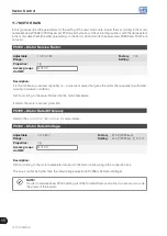
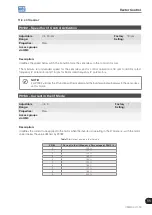
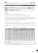
In that group are the parameters that are related to the motor and can be estimated by the inverter during the
self-tuning routine.
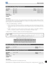
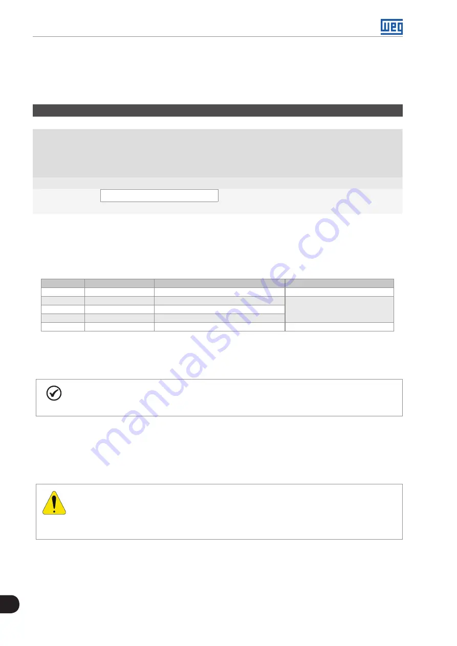
P0408 – Run Self-Tuning
Adjustable
Range:
0 = No
1 = No Rotation
2 = Run for I
m
3 = Run for T
m
4 = Estimate T
m
Factory
Setting:
0
Properties:
cfg, Vector and VVW
Access groups
via HMI:
MOTOR
Description:
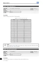
By changing from the factory setting to one of the 4 available options, it is possible to estimate the value of the
parameters related to the motor being used. Refer to the next description for more details on each option.
Table 11.5:
Self-tuning options
P0408
Self-tuning
Control Type
Estimate Parameter
0
No
–
–
1
No Rotation
Sensorless vector, with encoder or V V W
P0409, P0410, P0411,
P0412 and P0413
2
Run for I
m
Sensorless vector or with encoder
3
Run for T
m
Vector with encoder
4
Estimate T
m
Vector with encoder
P0413
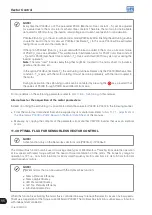
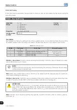
P0408=1 – No rotation:
The motor stands still during the self-tuning. The P0410 value is obtained from a table,
valid for WEG motors up to 12 poles.
NOTE!
Therefore P0410 must be equal to zero before initiating the self-tuning. If P0410≠0, the self-tuning
routine will keep the existent value.
Note:
When using another brand of motor P0410 must be adjusted with the adequate value (no load motor
current) before initiating the self-tuning.
P0408=2 – Run for Im:
The P0410 value is estimated with the motor rotating. It must be executed without load
coupled to the motor. P0409, P0411 to P0413 are estimated with the motor standing still.
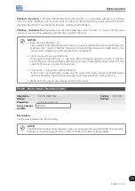
ATTENTION!
If the option P0408=2 (Run for I
m
) is performed with the load coupled to the motor, an incorrect
value of P0410 (Im) may be estimated. This will implicate in estimation error for P0412 (Rotor time
constant - T
r
) and for P0413 (Mechanic time constant – T
m
). Overcurrent fault (F071) may also occur
during the inverter operation.
Note:
The term “load” includes everything that might be coupled to the motor shaft, for instance, gearbox,
inertia disk, etc.
Summary of Contents for CFW700
Page 2: ......
Page 4: ......
Page 8: ...Summary...
Page 34: ...2 General Information 2 4 CFW700...
Page 38: ...3 About the CFW700 3 4 CFW700...
Page 56: ...7 Starting up and Settings 7 4 CFW700...
Page 58: ...8 Available Control Types 8 2 CFW700...
Page 78: ...10 VVW Control 10 8 CFW700...
Page 158: ...13 Digital and Analog Inputs and Outputs 13 28 CFW700...

