background image

33

KEY PART 

NO. NO. 

DESCRIPTION

KEY PART 

NO. NO. 

DESCRIPTION

NOTE:

 All component dimensions given in U.S. inches

         1 inch = 25.4 mm

RIDING MOWER - -CATALOG NO.   WE261  

DRIVE

–  –    532 43 61-44    SERVICE KIT, TRANSAXLE

1  

532 43 64-98 

WHEEL ASM (REAR)

2  

532 12 17-48 

WASHER, 16 GA.

3  

812 00 00-01 

E-CLIP

4  

532 12 35-83 

KEY. SQUARE

5  

532 42 79-39 

WELDMENT. DRIVE AXLE

6  

532 42 80-69 

CHAIN DRIVE

7  

532 42 78-73 

SPROCKET. 9 TOOTH  


SPLINED

8  

812 10 00-09 

RING, SNAP

10  

532 42 88-76 

DIFFERENTIAL ASM

11  

532 00 13-70 

WASHER, THRUST

12  

532 43 06-45 

CHAIN, PRIMARY DRIVE

13  

532 43 08-45 

BUSHING

14  

532 42 79-46 

BRACKET, CARRIER

15  

532 12 47-93 

BEARING ASM

16  

532 42 79-26 

SHAFT INPUT

17  

532 42 81-06 

WHEEL, FRICTION A5M

18  

532 42 47-59 

ARM, SHIFT

19  

532 43 08-70 

ROD, BYPASS

20  

532 42 79-97 

BRACE CARRIER REAR

21  

532 42 80-77 

SPRING, CARRIER

22  

532 42 80-76 

SPRING, BRAKE

23  

532 43 13-74 

SPRING, BYPASS

24  

532 42 79-95 

BRACE CARRIER BOX

25  

532 42 83-03 

LINK, SHIFT

26  

532 42 98-16 

ARM. CLUTCH

27  

532 42 90-53 

WELDMENT SHIFT LEVER

28  

532 42 83-02 

SUPPORT, SHIFT LEVER

29  

532 17 48-40 

WASHER, NYLON

30  

532 18 39-00 

HUB SHIFT LEVER

31  

532 42 90-55 

SPACER, NYLON

32  

532 42 84-64 

MNTG BRKT. SHIFT ARM

33  

532 42 84-61 

BRACKET, SHIFTER FLEX

34  

532 42 84-62 

TUBE SHIFT ARM

35  

532 19 64-92 

GRIP, HANDLE

36   

872  11  04-06 

BOLT, CARRIAGE - 114-20 X 3/4

37  

873 80 04-00 

NUT NYLON LOCK 114-20

38  

532 16 54-92 

BOLT, SHOULDER

39  

874 78 04-12 

BOLT, 1/4-20 X 3/4

40  

810 04 04-00 

WASHER, LOCK

41  

819 09 12-10 

WASHER FLAT

42  

532 16 60-02 

WASHER, SERRATED

43  

873 68 04-00 

NUT, CROWN LOCK 114-20

45  

817 49 04-36 

SCREW 1/4-20 X 2 114

46  

819 09 10-16 

WASHER

47  

817 49 04-20 

SCREW, 1/4-20 X 1 1/2

48  

532 43 02-49 

PLATE BRAKE ANTI - ROTATE

49  

532 43 02-45 

SPRING, BRAKE RETURN

50  

532 42 80-21 

ARM, BRAKE

51  

532 43 02-47 

SPACER RETURN

52  

532 42 80-78 

CALIPER, BRAKE ASM

53  

877 01 08-10 

PIN, DOWEL 1/4

54  

532 42 80-19 

PLATE, BRAKE PAD

55  

532 42 80-17 

PUCK BRAKE

56  

532 43 52-53 

ROTOR, BRAKE

57  

532 42 80-16 

CAP, BRAKE CALIPER

58  

532 12 47-88 

PIN, RETAINER

59  

817 49 05-08 

BOLT, 5/16-16 X 112

60  

532 42 84-60 

CABLE, BRAKE

61  

532 42 79-45 

WELDMENT, PEDAL

62  

532 42 96-78 

ROD, PARKING BRAKE

63  

877 10 08-12 

PIN, .25 X .75 CLEVIS

64  

876 02 02-08 

PIN, 1/16 DIA. COTTER

65  

532 42 93-25 

BRACKET, BRAKE SUPPORT

66  

532 42 96-94 

COVER PEDAL

67  

532 42 96-93 

COVER, BRAKE PEDAL

68  

817 49 04-06 

SCREW, 1/4-20 X 3/8

69  

532 42 80-70 

BRAKE CABLE MOUNT

70  

817 00 05-12 

BOLT, 5/16-18 X 3/4

71  

532 43 64-99   CAP HUB AXLE

72  

812 00 00-02 

E RING #5133-62

73  

532 42 95-19 

SPROCKET II TOOTH  


SPLINED

Summary of Contents for 532 43 32-03

Page 1: ...ator s Manual 532 43 32 03 Rev 10 26 RIDING MOWER SIDE DISCHARGE ELECTRIC START IMPORTANT Read and follow all Safety Rules and Instructions before operating this equipment Catalog No WE261 Patents Pen...

Page 2: ...al sale Battery must be maintained in accordance with the instructions furnished 4 The Warranty does not apply to any products used for rental or commercial purposes 5 This Warranty applies only to pr...

Page 3: ...ly in daylight or good artificial light Do not operate the machine while under the influence of alcohol or drugs Watch for traffic when operating near or crossing roadways Use extra care when loading...

Page 4: ...ud denly roll over if a wheel is over the edge or if the edge caves in III CHILDREN Tragic accidents can occur if the operator is not alert to the presence of children Children are often attracted to...

Page 5: ...g condition Never tamper with safety devices Check their proper operation regularly Keep machine free of grass leaves or otherdebrisbuild up Cleanoilorfuelspill age and remove any fuel soaked debris A...

Page 6: ...ned in effective working order by the operator InthestateofCaliforniatheaboveisrequired by law Section 4442 of the California Public Resources Code Other states may have similar laws Federal laws appl...

Page 7: ...cture tires on unit HOW TO SET UP YOUR RIDING MOWER INSTALL STEERING COLUMN 1 Insert steering shaft into mount and se curely fasten with bolt washer and nut provided 2 Insert pin into hole in steering...

Page 8: ...ob Flat Washer 4 Pivotseatandpanforwardandassemble adjustment knob and flat washer loosely Do not tighten 5 Lower seat into operating position and sit in seat 6 Slide seat until a comfortable position...

Page 9: ...g Check mower belt Be sure it is routed properlyaroundpulleysandinsideallbelt keepers Check wiring See that all connections are still secure and wires are properly clamped Beforedrivingridingmower bes...

Page 10: ...afety inform ation about hazards which can result in death serious injury and or property damage DANGER indicates a hazard which if not avoided will result in death or serious injury WARNING indicates...

Page 11: ...HEIGHT ADJUSTMENT LEVER Used to adjust mower cutting height IGNITION SWITCH Used for starting and stopping the engine LIFT LEVER PLUNGER Used to release height adjustment lever when changing its posi...

Page 12: ...plunger with thumb and move lever to desired position The cutting height range is approximately 1 1 2 to 4 The heights are measured from the ground to the blade tip with the engine not running These...

Page 13: ...Operation System ROS Any attempt by the operator to travel in the reverse direc tion with the deck clutch engaged will shut off the engine unless ignition key is placed in the ROS ON position WARNING...

Page 14: ...than fifteen seconds per minute NOTE If at high altitude above 3000 feet or in cold temperature below 32 F the fuel mixture may need to be adjusted for best performance TO TRANSPORT When pushing or t...

Page 15: ...should be mowed twice to reduce load and possible fire hazard from dried clippings Make first cut relatively high the second to the desired height RECOIL STARTING SYSTEM This unit is equipped with an...

Page 16: ...ugandcleanairfilterassureproper air fuel mixture and help your engine run better and last longer BEFORE EACH USE 1 Check engine oil level 2 Check brake operation 3 Check tire pressure 4 Check operator...

Page 17: ...are working properly If your riding mower does not function as described repair the problem immediately The engine should not start unless the brake pedal is fully depressed and the deck clutch lever...

Page 18: ...il level before starting the engine and after each eight 8 hours of operation Tighten oil fill cap dipstick securely each time you check the oil level ENGINE LUBRICATION Only use high quality detergen...

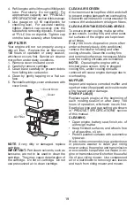
Page 19: ...nstalled NOTE Operating the engine with a blocked grass screen dirty or plugged cooling fins and or cooling shrouds removed will cause engine damage due to overheating CLEAN AIR SCREEN Air screen must...

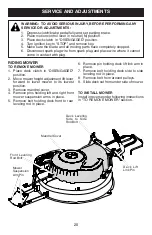
Page 20: ...WER 1 Place deck clutch in DISENGAGED position 2 Move mower height adjustment lift lever forward to lower mower to its lowest position 3 Remove mandrel cover 4 Remove pins holding left and right front...

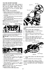
Page 21: ...mower Measuredistance F directlyinfront and behind the mandrel at bottom edge of mower housing as shown F F To lower front of mower housing turn nuts G and H clockwise When distance F is 1 8 to 1 2 l...

Page 22: ...ire dry rot and corrosion Retaining Ring Dust Cover Washer Square Key rear wheel only Rotor Nut Brake Pad NOTE Feeler gauge may be necessary to get correct measurement REAR WHEEL 1 Block up Rear axle...

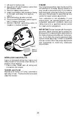
Page 23: ...plug in fuse The fuse holder is located under the fender ENGINE Your engine speed has been factory set Do not attempt to increase engine speed or it may result in personal injury If you believe thatt...

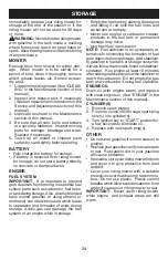
Page 24: ...eads to separation and formation of acids during storage Acidic gas can damage the fuel system of an engine while in storage Empty the fuel tank by starting the engine and letting it run until the fue...

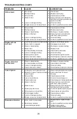
Page 25: ...ce solenoid or starter 9 Faultyoperatorpresenceswitch es 9 Contact a qualified service center Engine clicks but will not start 1 Weak or dead battery 1 Recharge or replace battery 2 Corroded battery t...

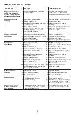
Page 26: ...rass to dry before mowing 3 Mower deck not level 3 Level mower deck 4 Low uneven tire air pressure 4 Check tires for proper PSI 5 Worn bent or loose blade 5 Replace sharpen blade Tighten blade bolt 6...

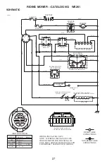
Page 27: ...IRING INSULATED CLIPS NOTE IF WIRING INSULATED CLIPS WERE REMOVED FOR SERVICING OF UNIT THEY SHOULD BE RE INSTALLED TO PROPERLY SECURE YOUR WIRING IGNITION SWITCH CIRCUIT POSITION OFF B A1 RUN OVERRID...

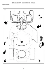
Page 28: ...28 RIDING MOWER CATALOG NO WE261 ELECTRICAL 11 LRV1 10 9 8 12 13 7 1 2 3 4 6 5...

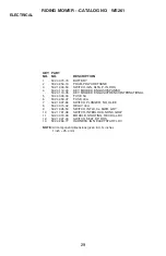
Page 29: ...INTERNATIONAL 5 532 43 33 30 FUSE 5A 6 532 42 59 37 FUSE 40A 7 532 16 07 84 SWITCH PLUNGER NO OLIVE 8 532 43 15 42 RELAY 40A 9 532 10 95 53 SWITCH INTLK CL MWR GRY 10 532 17 61 38 SWITCH INTERLOCK NO...

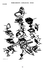
Page 30: ...1 CHASSIS 10 11 3 4 5 7 9 8 1 2 12 13 49 14 15 16 17 18 19 20 21 22 23 24 24 25 26 27 28 29 30 31 32 33 34 35 36 37 38 39 39 40 40 41 41 42 43 44 45 45 50 50 45 45 45 45 45 45 6 46 46 45 45 45 46 48 4...

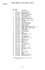
Page 31: ...8 15 LEVER SWITCH 22 532 42 88 26 DECK CLUTCH ASM 23 532 14 98 46 KNOB 24 532 41 63 58 SCREW NO 10 25 872 14 04 24 BOLT CARRIAGE 1 4 20 X 3 26 873 51 04 00 NUT 1 4 20 27 532 43 00 87 SPACER ENGINE 28...

Page 32: ...5 6 7 72 8 8 1 2 2 3 4 5 6 7 8 73 8 12 13 13 70 70 14 14 15 71 15 16 17 18 19 20 21 22 23 24 24 25 26 27 28 29 30 31 32 33 34 35 36 37 37 38 38 38 39 40 41 42 43 70 45 46 47 48 49 50 51 52 53 54 55 5...

Page 33: ...T SHIFT ARM 33 532 42 84 61 BRACKET SHIFTER FLEX 34 532 42 84 62 TUBE SHIFT ARM 35 532 19 64 92 GRIP HANDLE 36 872 11 04 06 BOLT CARRIAGE 114 20X3 4 37 873 80 04 00 NUT NYLON LOCK 114 20 38 532 16 54...

Page 34: ...34 RIDING MOWER CATALOG NO WE261 STEERING 10 11 2 2 4 6 6 7 7 9 9 9 1 2 30 3 1 2 30 3 4 4 5 29 8 8 8 12 13 14 15 16 17 18 19 19 20 21 22 28 23 24 25 26 27 LRV Steering_1_r2...

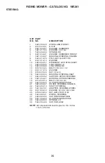
Page 35: ...10 16 WASHER 15 873 80 05 00 NUT 5 16 18 16 532 42 80 44 BUSHING STEERING SNAP 17 532 42 82 52 SUPPORT UPPER STEERING 18 532 19 52 27 BUSHING UPPER STEERING 19 817 00 05 12 BOLT 5 16 18 X 3 4 20 532...

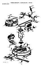
Page 36: ...ER CATALOG NO WE261 MOWER DECK 10 11 1 2 3 4 5 7 9 8 12 13 41 14 15 16 16 17 17 17 40 17 45 18 18 19 19 19 19 20 20 21 22 23 42 24 25 26 27 27 28 29 30 31 32 33 34 35 36 37 37 38 39 39 LRV Deck_1_r4 4...

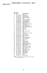
Page 37: ...32 X 1 3 16 22 532 42 93 50 LINK DECK 23 873 93 06 00 NUT LCK 3 8 16 24 532 42 95 31 SPRING DECK 25 532 12 47 88 PIN 26 532 18 76 90 SPACER MANDREL 27 532 17 39 84 BOLT MANDREL 28 532 40 02 34 NUT LOC...

Page 38: ...DEFLECTOR 5 532 43 44 57 DECAL WARNING ENGINEGUARD 6 532 43 53 48 DECAL STRBRCKT INSTALL BOOT 532 43 24 79 DECAL BYPASS 532 43 32 03 MANUAL OPERATOR ENGLISH 532 43 36 32 MANUAL OPERATOR SPANISH 532 4...

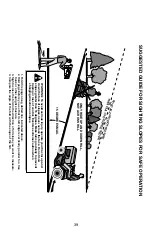
Page 39: ...never across the face Do not mow slopes greater than 15 degrees Make turns gradually to prevent tipping or loss of control Exercise extreme caution when changing direction on slopes 1 Fold this page a...

Page 40: ...umber Manufacturer s I D Number b Description of part For Technical Assistance call 1 800 829 5886 For a Parts Manual go to our website www weedeater com NOTE HOP provides parts and service through it...

Reviews: