Section B - Components
JBE(X) Manual
Page 12
attach the burner to the vessel. A fiberglass rope gasket
(3/8” dia) is used to seal the mounting flange to the
refractory front plate. The rope is wrapped around the
flange several times to seal the full diameter of the flange.
In addition, a ceramic blanket is used in front of the gas
manifold to protect it from the internal temperatures of
the furnace. The ceramic blanket should be 1” thick by 2”
wide (Figure B-11).
Gas Spuds
A series of gas spuds are used to direct the gas into
the air stream. These gas spuds are located around the
circumference of the gas manifold. The gas spuds are
arranged in a manner that gives good mixing of the air
and fuel in conjunction with the diffuser.
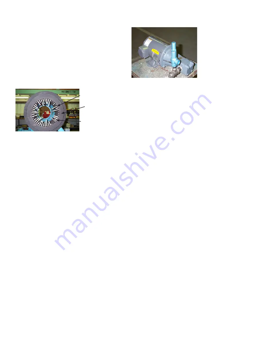
Long Gas Spuds
Gas
Manifold
Short Gas Spuds
Figure B-12 Gas Spuds in Gas Manifold
Gas spud arrangement can change by fuel type, input
and NOx level. In some cases, field adjustment of these
spuds is required to meet different furnace configurations
and field conditions.
The gas spuds are stainless steel pipe nipples (1/8” NPT)
that are screwed into the gas manifold. Some of the holes
in the manifold are plugged with pipe plugs. “Never-
Seize” must be used on the pipe threads to prevent them
from seizing due to the heat at this location.
5. Oil Fuel Components
There are two different types of oil firing available; air
atomizing and pressure atomizing. The air atomizing
system requires an air compressor, or as an alternate,
plant air or steam.
The pressure atomizing system uses higher oil pressures
to atomize the oil. It will use return flow oil nozzles in a
tight cluster to provide atomization.
Oil Pump
The oil pump is used to supply oil to the nozzle at
sufficient flow and pressure. The oil pump is provided as
a separate item that must be mounted, wired and piped.
The assembly consists of the pump, motor, coupling,
pump-motor bracket and oil pressure regulator. The
motor base mount is used to secure the assembly.
Oil Pressure Regulator
An oil pressure regulator is used to maintain constant oil
pressure to the burner. It is adjusted to provide the oil
pressure needed at the nozzle. On small sizes, this may
be integral to the oil pump.
Oil Supply Pressure Gauge
This indicates the oil supply pressure from the pump.
Oil Train
The oil train contains the safety shut-off valves, pressure
switches and other components that may be required
for the specific installation, insurance codes and local
regulations and can vary from burner to burner. Oil trains
are designed for each application and a unit-specific oil
train drawing is provided with each unit. Details of the
components are provided with each burner.
Oil Safety Shutoff Valve
Each oil train has two shutoff valves. The valves can
be either solenoid or motorized type and can have an
optional POC (proof of closure) switch.
Low Oil Pressure Switch
This switch is set to a pressure below the expected oil
pressure and will trip if the oil pressure drops below this
level, shutting down the burner.
High Oil Pressure Switch
This optional switch is set to a pressure above the
expected oil pressure and will trip if the oil pressure rises
above this level, shutting down the burner.
Manual Ball Valve
A manual valve is provided in the oil line to perform
testing of the safety controls as part of the normal
startup procedures.
Oil Flow Control Valve
The oil flow control valve regulates the flow of oil to the
nozzle. In the air atomizing system, the control valve is
in the piping to the nozzle, directly regulating the flow of
oil. In the pressure atomizing system, the control valve is
located in the return line from the nozzle, controlling the
return flow, to indirectly control the oil flow to the nozzle.
The oil flow control valve modulates with the air damper
to provide different input rates. On a single point
positioning system (linkage), it is connected to the jack
shaft and uses a fuel cam to make fine adjustments to
fuel flow. With a parallel positioning system (linkageless),
an actuator is connected to the oil control valve and
modulated by electronic control to the desired position.
Figure B-13
Oil Pump and
Regulator


