


11
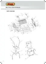
COMPONENTS
1.
Top Handle
2.
Centre Handle
3.
Lower Handle
4.
Grass Collector
5.
Rear Roller
6.
Cutting Cylinder
7.
Height Adjuster
8.
Front Roller
9.
Delivery Plate
10.
Cylinder Adjuster
* Image may vary from actual machine
1
2
3
4
5
6
7
8
10
9
ASSEMBLY
Remove the machine and contents from the carton. Be sure the carton is empty before discarding.
If you require assistance with regards to the contents or operation of the machine, please contact us:
Tel: 01793 333212
Email: [email protected]
Opening hours weekdays: February to October 8:30am - 5:30pm / November to January 8:30am - 5:00pm
(Closed Bank Holidays)
FITTING THE HANDLE
CAUTION
This operation must be done close to the cutting cylinder blade. We strongly recommend the use of thick
gardening gloves on both hands and the lawnmower body is secured to stop the cutting cylinder blade from
rotating.
1.
Align the holes on both upper handles with those on the middle handles.
2.
Secure both handles together using wingnuts & bolts provided.
3.
Locate the fixing peg, positioned within the main body recess on the lawnmower and slide the appropriate
lower handle over the peg.
INSTRUCTION MANUAL
Summary of Contents for WEH12R
Page 17: ...17 Notes ...
Page 18: ...18 PARTS DIAGRAM INSTRUCTION MANUAL ...
Page 21: ...21 Notes ...
Page 28: ...Webb Lawnmowers Murdock Road Dorcan Swindon Wiltshire SN3 5HY ...


