background image

4 | Scope of delivery

6 / 26

5111966A ISI Webasto Unite (EN)

4

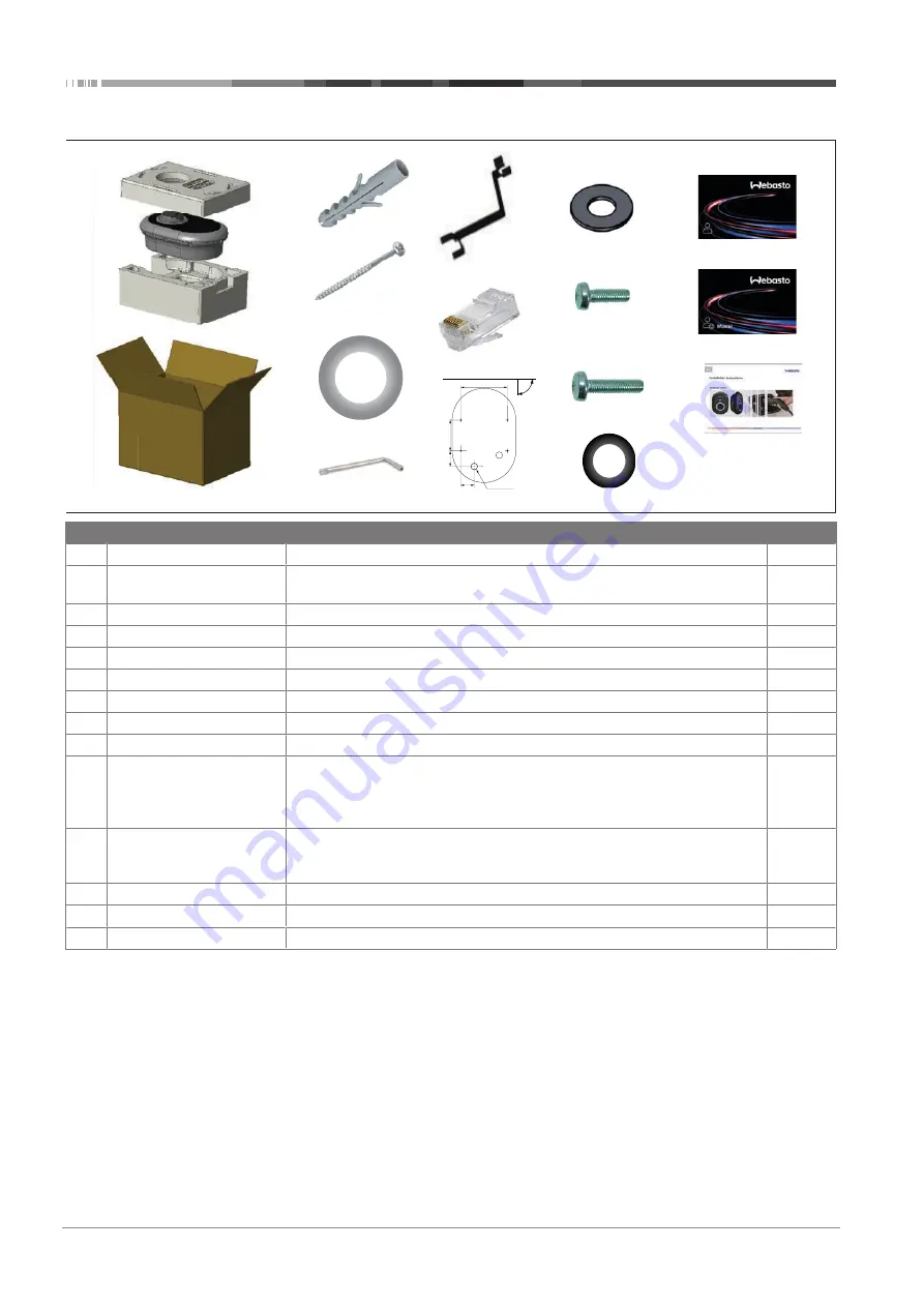
Scope of delivery

65,50

75,00

150,00

226,00

90º

USE Spirit level for alignment

Cable outlet

Print scale 1/1

1

2

3

4

5

6

7

8

9

10

11

14

13

12

Pos. Item(s)

Usage

Quantity

1

Dowels (M8 x 50, plastic)

To mount the charging station on the wall.

4

2

Torx T25 security screw (M6
x 75)

To mount the charging station on the wall.

4

3

Gasket for screw (6 x 75)

To mount the charging station on the wall with the correct IP.

4

4

Torx T20 security L‑wrench

Wrench for screws to mount the charging station on the wall with the correct IP.

1

5

Wrench

To fasten and unfastening the cable glands.

1

6

RJ45 Male connector

LAN cable connection (optional).

1

7

Mounting template

To mount the charging station to a wall.

1

8

O-ring

To mount the charging station to a pole.

3

9

Screw (M6 x 20)

To mount the charging station to a pole.

3

10

Screw (M6 x 30)

To mount the charging station, and providing earth continuity for chargers
mounted on a metal surface. This screw must be inserted into the bottom hole of
charging station on the wall. Place a rubber ring (11) below this screw to fix the
ground cable.

1

11

IP Rubber

To fix the ground cable with the M6 x 30 screw. This rubber ring must be placed
right-down the wall-mount hole of charging station, under the ground cable and
the M6 x 30 screw.

1

12

User RFID Card

To start and stop charging.

2

13

Master RFID Card

To add and remove user RFID Cards to and from the local RFID list.

1

14

These instructions

To install the charging station safely and adequately.

1

Summary of Contents for Unite

Page 1: ...Webasto Unite Important Information on Operating and Installation Instructions 2 Webasto Charging Solutions ...

Page 2: ... Using a 3 phase AC mains connection 9 6 5 Using the cable glands 9 6 6 Adjusting the current limiter 10 6 7 Setting the DIP switches 10 6 8 Using the Mode selection switch 13 6 9 Setting up Load shedding Potential free contact 13 6 10 Monitoring welded relay contact failures 14 6 11 Resetting RFID card lists and registering new master RFID cards 14 6 12 Configuring a charging station s Ethernet p...

Page 3: ... the Webasto Charger Setup app and configure your charging station 1 For installation Webasto Charger Setup 2 For operation Webasto ChargeConnect 4 5 6 Scan the QR code on the label in the Quick Start Guide or type in the Wi Fi password manually Open the ChargeConnect app and follow the steps to connect the charging station to the ChargeConnect Cloud Plug in and enjoy exploring your charging stati...

Page 4: ...es for l Improper use l Repairs carried out by an electrician not contracted by Webasto l Use of non original spare parts l Unauthorised conversion of the unit without permission from Webasto l Installation and commissioning by unqualified staff not an electrician l Improper disposal after decommissioning NOTE In case of any claims defects or damage to your pro ject you must contact your direct co...

Page 5: ...wash installations high pressure cleaners or garden hoses l Protect the Webasto Unite against damage caused by sub zero temperatures hail or similar We would like to refer you to our IP protection class at this juncture IP54 l The Webasto Unite is suitable for use in areas without access restrictions l Protect the Webasto Unite from direct sunlight The charging current may be reduced at high tempe...

Page 6: ...connection optional 1 7 Mounting template To mount the charging station to a wall 1 8 O ring To mount the charging station to a pole 3 9 Screw M6 x 20 To mount the charging station to a pole 3 10 Screw M6 x 30 To mount the charging station and providing earth continuity for chargers mounted on a metal surface This screw must be inserted into the bottom hole of charging station on the wall Place a ...

Page 7: ... l Do not mount your charging station on the ceiling or on a sloping wall l Use the specified wall mounting screws and other accessor ies l This charging station is classified as indoor and is outdoor installation compatible If the charging station is installed outside a building the hardware that is used to connect the cables to the charger must be compatible with outdoor use and the charging sta...

Page 8: ...rque of 2 5 Nm B A 3 If you mount the charging station on a conductive metal surface such as a metal pole you must make a connection to the earth using an extension wire for the earth ground and the screw at the lower right 4 Change the position of the grounding wire from A to B to ensure grounding Insert the plastic support this is the IP rubber supplied in the unit s accessory pack into the fixi...

Page 9: ... grounding wire from A to B to ensure grounding Insert the plastic support this is the IP rubber supplied in the unit s accessory pack into the fixing hole position B Secure the grounding cable using an M6 x 30 screw which is in the artwork pack This screw also secures the unit to a conductive metal surface where applicable 5 Tighten the cable glands before closing the charging sta tion cover See ...

Page 10: ...ent limit Value 22 kW 0 1 phase 10 A 1 13 A 2 16 A 3 20 A 4 25 A 5 30 A 6 32 A 7 X X Switch position Phase Current limit Value 22 kW 8 3 phase 10 A 9 13 A A 16 A B 20 A C 25 A D 30 A E 32 A F X X Required circuit breaker on AC mains Charging Station Current Limiter Setting C Curve MCB miniature circuit breaker 10 A 13 A 13 A 16 A 16 A 20 A 20 A 25 A 25 A 32 A 30 A 40 A 6 7 Setting the DIP switches...

Page 11: ...mizer meter B COM 6 CN2 6 Power optimizer meter A COM 7 CN2 7 8 CN2 8 1 Mount the wiring according to the illustration and table above Charging is disabled when the external relay contacts are in the open position NOTE DIP switch settings DIP switch settings are optional All settings can be changed by using the Setup App or the web configura tion interface see Unite Configuration Interface u The m...

Page 12: ...N Enabled OFF Disabled 3 To enable the locked cable function toggle DIP switch 3 into the ON position using a pointed spudger or a similar plastic pointed tool The DIP switch location is shown in the above figure NOTE DIP switch settings DIP switch settings are optional All settings can be changed by using the Setup App or the web configura tion interface see Unite Configuration Interface u The mo...

Page 13: ...tion point 1 ON 2 3 4 5 6 ON OFF DIP switch positions 4 5 and 6 correspond to the binary digits of the maximum current value as shown in the table below When DIP switches 4 5 and 6 are in the OFF position then the power optimizer functionality is disabled DIP switch 4 DIP switch 5 DIP switch 6 Current limit value OFF OFF OFF Power optimizer disabled OFF OFF ON 16 OFF ON OFF 20 OFF ON ON 25 ON OFF ...

Page 14: ...upled to an RCCB or MCB at the fuse box of the charging station CN33 Connect the shunt trip module to the charging station 6 11 Resetting RFID card lists and registering new master RFID cards This section explains how to reset the local RFID card list and how to register new master RFID cards in standalone usage mode If you have lost your master RFID card and need to define a new master RFID card ...

Page 15: ...13 Enabling and disabling the web configuration interface To enable or disable the Web Configuration Interface 1 ON 2 3 4 5 6 Toggle 1 Switch off the charging station 2 Open the charging station s front cover 3 Put DIP switch number 3 in the OFF position to disable the web configuration in terface in the ON position to enable the web configuration in terface 4 Close the charging station s front co...

Page 16: ...red every second for 60 seconds Master card config mode Local card list reset 2 sec Blinks blue every 2 seconds Waiting to tap a User RFID card or configure Drive green from a smartphone 2 x Blinks green 2 times User RFID Card added to local RFID list 2 x Blinks red 2 times User RFID card removed from local RFID Green glowing Authorized RFID Card is tapped while the charging cable is con nected 30...

Page 17: ... add delete a given user RFID card If you do not make any con figuration changes within 60 seconds the charging station will exit from its configuration mode and will return to its previous mode You must repeat these steps for each user RFID card ad dition deletion 7 3 2 2 Vehicle connecting charging No LED Indication Make sure that your vehicle and the charging station are ready for charging No L...

Page 18: ...arging station are ready for charging No LED Indication Insert the charging plug into the vehicle inlet and the charging station socket outlet 4 sec Blinks blue Tap the RFID card on the RFID reader You may start charging with a card which is registered with your charging operator Green glowing You may start charging with a card that has been authorized before If the RFID Card is authorized by OCPP...

Page 19: ...upported by the charging station If it is also supported by the connected server then charging process may be initiated terminated remotely 7 4 3 2 Hard reset soft reset If the charging station is not working properly the service pro vider may reset the appliance with this feature There are two types of resets Software or hardware reset may be selected 7 4 3 3 Unlocking the socket If the charging ...

Page 20: ...on both ends of the cable Make sure your electric vehicle is in charging mode 4 sec The status information LED blinks in red This error is displayed if your vehicle is equipped with a bat tery type that requires ventila tion This charging station is not suit able to charge such battery types NOTE Troubleshooting If you need further assistance in troubleshooting please contact your contractual part...

Page 21: ...pment to be reused or valuable constitu ent parts of broken equipment to be recycled The aim of this is to contribute to more efficient use of resources and more sus tainable development Moreover it is only through separate col lection that hazardous elements of the equipment such as CFCs or mercury can undergo sufficient treatment thereby avoiding negative impacts on the environment and human hea...

Page 22: ... the weather conditions on the installation date sun rain overcast snow or other ______________________________________________ The location of the charging station should be selected such that vehicles cannot inadvertently collide with it The legal requirements for electrical installations fire protection safety regulations and escape routes have been met The customer user was informed how the We...

Page 23: ...h Asterisk can be one of the following SO with normal socket SH with shuttered socket 12 2 Dimensional drawings 12 3 MID model 1 3 4 5 2 6 7 8 1 RFID card reader Radio Frequency Identification 2 Status indicator LED 3 Socket outlet with shutter 4 Product label 5 MID meter display Measuring Instruments Directive 2014 32 EU 6 Charging station supply inlet gland nut 7 Charging station communication c...

Page 24: ... mm2 Flexible with wire end ferrule 2 5 10 mm2 Max external dimension Ø 18 25 mm Connectivity Ethernet 10 100 Mbps Ethernet Wi Fi Wi Fi 802 11 a b g n ac Wi Fi specifications 2 4 GHz Band Standard 802 11b 802 11g 802 11n 802 11n Modulation DSS CKK OFDM OFDM OFDM Data rate 1 2 5 5 11 6 9 12 18 24 36 48 54 MCS0 7 HT20 MCS0 7 HT40 Channel CH 1 13 CH 1 13 CH 1 13 CH 1 13 Power dBm 13 5 13 5 13 5 13 5 ...

Page 25: ...Mains Cable Dimensions For three phase models Ø 18 25 mm For one phase models Ø 13 18 mm Cable Inlets AC Mains Ethernet Modbus Environmental technical specifications Protection class IP54 Impact protection IK10 Usage conditions 35 C to 55 C without direct sunlight 5 95 relative humidity non condensing 0 4 000 m ...

Page 26: ...com en int To provide feedback in English or German on this document please email the Tech Doc and Translation team feed back2tdt webasto com www webasto com 5111966A Webasto Charging Hotline 800 CHARGING 00800 24274464 Webasto Thermo Comfort SE Postfach 1410 82199 Gilching Germany Company address Friedrichshafener Str 9 82205 Gilching Germany UK only Webasto Thermo Comfort UK Ltd Webasto House Wh...

Reviews: