background image

Chapter 1

Introduction

Summary of Contents for 900EX

Page 1: ...Installation Operation and Maintenance Manual EV Test Systems 900 EX ...

Page 2: ...AY VARY NO PORTION OF THESE MATERIALS MAY BE DUPLICATED USED OR DISCLOSED WITHOUT PRIOR WRITTEN PERMISSION FROM WEBASTO CHARGING SYSTEMS INC DISCLAIMER THIS MANUAL INCLUDES THE LATEST INFORMATION AVAILABLE AT THE TIME OF PRINTING WEBASTO CHARGING SYSTEMS INC RESERVES THE RIGHT TO MAKE CHANGES TO THIS MANUAL AND OR PRODUCT WITHOUT FURTHER NOTICE CHANGES OR MODIFICATIONS TO THIS PRODUCT NOT COMPLETE...

Page 3: ... above and have it available when contacting Webasto customer support The serial number can be found on the nameplate rating label on the upper left corner of the unit Webasto EV Test Systems Customer Support 1 866 767 4242 info us webasto charging com OWNER S RECORD Model 900 EX Serial number s n Purchase date 22855 03 04 ...

Page 4: ...mponents 8 2 4 AC Inverter Functions Controls 9 2 5 DC Converter Functions Controls 13 2 6 Technical Specifications 17 3 INSTALLATION 19 3 1 On Site Installation 20 4 OPERATION 23 4 1 Channel to Channel Operation 25 4 2 Planning 25 4 3 Choosing a Load Configuration 26 4 4 Choosing Operating Limits 30 4 5 Operating the System 31 4 6 System Start Up 33 4 7 Connecting Load Selecting Configuration 33 ...

Page 5: ...RY OF TERMS 45 A 1 Glossary of Terms 46 Appendix B DC I O CONNECTOR ASSEMBLY 51 B 1 Standard Unit with CAMLOCKS 52 B 2 No CAMLOCKS Unit 53 Appendix C 900 EX REMOTE VOLTAGE SENSE OPERATION 55 C 1 Remote Voltage Sense RVS Operation 56 Appendix D HIGH VOLTAGE INTERLOCK WIRING 59 Appendix E INDEX 61 ...

Page 6: ...iv ...

Page 7: ...Chapter 1 Introduction ...

Page 8: ... and observed Indicates information about safety practices which if not followed may result in serious injury or death Indicates information about safety practices which if not followed could result in personal injury fire or equipment overheating Indicates helpful information for installation or usage but does not contain personnel or equipment safety related information ...

Page 9: ...wer is on An incorrectly installed or improperly grounded unit is a hazard Depress and latch the Emergency Off Switch Turn off local disconnect on the left side of the unit Leave off for at least five 5 minutes to allow high voltage to discharge Do not operate the unit if there is physical damage to the unit coupler or cable Do not subject the cable to damage or stress Do not step on the DC output...

Page 10: ...X is provided to allow a hardware monitor to shut down the 900 EX in the event of an unsafe battery condition Before attempting to service the system follow these steps 1 Turn off the Input Circuit Breaker or Main Disconnect Switch 2 Turn off local disconnect on the left side of the unit 3 Depress and latch the Emergency Off switch for at least five 5 minutes to allow the high voltage to discharge...

Page 11: ...Chapter 2 System Description ...

Page 12: ... meet the needs of both uni directional and bi directional operation Power is transferred from the utility to the load or from the load to the utility Using the utility to absorb power eliminates the need for external resistive loads and conserves energy that is normally lost In addition the 900 EX incorporates special power processing algorithms to perform a wide variety of tests 2 2 900 EX POWER...

Page 13: ...els Power Generation Equipment Testing Electric Components Power Supplies Generators Stationary Power Inverters Military Aerospace Life Run in Burn in Uninterruptable Power Supplies UPS Hybrid and Electric Vehicle Testing Powertrain Production Testing Medium Heavy duty EVs buses trucks military locomotives ...

Page 14: ...8 2 3 SYSTEM COMPONENTS Figure 1 and Table 2 illustrate and describe the 900 EX system components Figure 1 System Components ...

Page 15: ...ocks Channels A and B 10 DC Output Camlocks Option 11 Isolation Fault Detection 12 AC Diagnostic Port 13 Remote E Emergency Stop 14 Local E Emergency Stop 15 Power Button 16 Utility IN 2 4 AC INVERTER FUNCTIONS CONTROLS The AC Inverter interfaces the utility to an internal Intermediate DC Bus The Intermediate DC Bus voltage is regulated by the AC Inverter based on the maximum voltage expected by t...

Page 16: ...sponse in the inverter dynamics In addition references for the current are obtained from the utility waveforms thereby maintaining the AC Inverter as a true unity power factor interface regardless of line harmonics Figure 2 shows the AC Inverter front panel See Table 3 for a description of AC Inverter panel functions Figure 2 AC Inverter Front Panel The main circuit breaker must be switched off an...

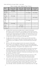
Page 17: ...ust be rotated counterclockwise to power the control system 2 4 1 ISOLATION FAULT DETECTION Internal Isolation is monitored with a separate circuit Prior to contactor closure this circuit monitors the impedance between the positive and negative intermediate busses and the chassis or earth ground Once the contactors have been closed and the Unit Under Test UUT is connected to the 900 EX the Isolati...

Page 18: ... red 3 Monitor After the bus voltage has risen to its set point the Isolation Monitoring circuit evaluates the isolation level of the high voltage power system If no faults are detected the system displays the Ready light green with steady illumination The system is now ready to be used 4 Bus Fault Bus Fault If loss of internal isolation is detected the isolation fault detection circuit will preve...

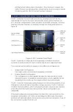
Page 19: ...to operate in two different configurations 1 Independent Configuration Two loads can be connected and separately controlled 2 External Parallel Configuration This configuration is called parallel because the two converter circuits internally function in parallel to provide higher current capability When operating in this mode use the output on both channel terminals The DC Converter incorporates s...

Page 20: ...PERATION INTERFACE The Remote Operation Interface is an isolated input based on the RS 232 communication standard and allows communication between the DC Converter and the 900 EX ROS The purpose of this interface is to provide status information and DC output measurements from the 900 EX to the ROS and to accept commands from the ROS For more information on the Remote Operation Interface please re...

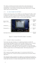
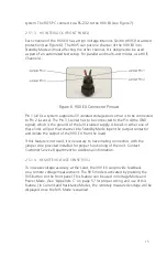
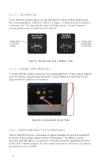
Page 21: ...of the V isolated supply A break in either one of these links will put that channel into Standby Mode open the output contactor and isolate the output of the 900 EX from the load If this feature is not used it is necessary to have mating connectors with the jumper wire provided installed for proper functioning of the unit Contact Customer Service Department for additional information 2 5 1 4 REMOT...

Page 22: ...r protocol provides an encapsulated form of the existing datalink used for remote operation see Figure 8 Contact Webasto s Customer Service Department for additional information Figure 8 Connected Ethernet Fiber 2 5 1 7 REMOTE EMERGENCY STOP OPERATIONAL Within the 900 EX there is a provision to allow installation of an external switch to control the emergency stop function of the system To enable ...

Page 23: ...tures Parameter Description Input Rating 3 Phase 480 V 440 V 415 V 400 V 380 V Current 344 A 375 A 398 A 413 A 435 A Frequency 60 Hz 50 60 Hz Isolation Transformer 288 KVA Internal Power Factor 0 95 Harmonic Distortion 3 70 Multiple User Interfaces Local HMI Serial CAN Ethernet Fiber Measured at full processing power Refer to product nameplate for input voltage ...

Page 24: ...nt 8 to 750 500 to 500 250 to 250 750 to 825 400 to 400 225 to 225 825 to 900 300 to 300 200 to 200 Parallel 8 to 750 1000 to 1000 250 to 250 750 to 825 800 to 800 225 to 225 825 to 900 600 to 600 200 to 200 Weight 6100 lb 2767 kg Dimensions 72 W x 76 5 H x 39 D 183 cm W x 194 cm H x 99 cm D ...

Page 25: ...Chapter 3 Installation ...

Page 26: ...To allow for adequate air flow there should be no obstructions on the right or left side of the unit 3 1 1 3 UTILITY REQUIREMENTS The input wiring block is located on the top left side of the 900 EX see Figure 10 A 3 diameter hole can be punched for a 3 conduit to accommodate 3 phase wires plus ground Input wire selection should be compliant to local electrical code Figure 10 Wiring and Ground Ins...

Page 27: ...21 3 1 2 VERIFY UNIT 3 1 2 1 INSTALLATION CHECKLIST Write down the unit serial number on the installation checklist Figure 11 Figure 11 Installation Checklist ...

Page 28: ...nding of Industrial and Commercial Power Systems Section 250 Grounding of NEC and all local codes and ordinances We recommend no more than 0 1 Ohms between all equipment and ground Use copper conductors and terminal lugs only 3 1 2 3VERIFY COOLANT LEVEL Verify coolant level before powering up the unit Coolant level shall be approximately 2 from the bottom of coolant reservoir 3 1 3 GENERAL OPERATI...

Page 29: ...Chapter 4 Operation ...

Page 30: ... under load If the external load contact opens put the 900 EX into Standby Mode before closing the external contact This can be achieved manually or via instructions in a script Failure to put the 900 EX in Standby Mode after the external contact is opened may cause serious damage to the equipment Use the High Voltage Interlock Connector to put the unit into Standby Mode When the high voltage inte...

Page 31: ...te with those provided on the 900 EX unit One cable should have red terminals on both sides and the other should have black connectors on both sides 2 Connect to Channel A Positive Red terminal first 3 Next connect to Channel A Negative Black terminal 4 Then connect to Channel B Positive Red terminal 5 Finally connect to Channel B Negative Black terminal 4 2 PLANNING Before testing with the 900 EX...

Page 32: ...ATION Some loads and test plans may require a particular configuration of the 900 EX load connections Figure 13 shows the Operating Limits for the following two configurations Independent and Parallel Each of the configurations is described in more detail below ...

Page 33: ...ntrolled separately Each load is connected from the positive terminal to the negative terminal of the appropriate output The name Independent is used due to the separate set up procedures required for each output and the independent control that each DC Converter has over its own output A single load may be connected in Independent Configuration i e either Load A or Load B with no change in functi...

Page 34: ...n in External Parallel Configuration the Parallel Configuration is selected on the front panel as seen in Figure 15 and a single load is connected to both the positive and negative output terminals Parallel Configuration is illustrated in Figure 15 Figure 15 Parallel Configuration ...

Page 35: ...een in Figure 16 When in Multi Unit Configuration the load is connected to both the positive and negative output terminals of each paralleled unit Multi Unit Screen is shown in Figure 16 and Configuration is illustrated in Figure 17 Figure 16 Multi Unit Screen Figure 17 Multi Unit Configuration ...

Page 36: ... By setting more restrictive Operating Limits the Operating Space is reduced When operating inside the limits of the Operating Space the DC Converter will control the output based on the selected Control Mode and value However if one of the boundaries of the Operating Space is reached the DC Converter will override the selected Control Mode and use the boundary condition as its internal Control Mo...

Page 37: ...oltage Control Mode as efficiently as possible at or near zero power 3 The sum of the upper and lower power limits must be no greater than the maximum power for the set voltage limit These values are 250 kW 225 kW and 200 kW for 750V 825V and 900 V limits respectively 4 The Operating Limits may not be outside the maximum limits of the DC Converter for the chosen configuration 5 The upper limit for...

Page 38: ... EX Operation Flow Chart The 900 EX is designed to make setup and operation as easy as possible while ensuring safety Once the system main power is on the front panel HMI will start up and connect to the DC controller ...

Page 39: ...mpletely power down the unit press the Main Power Off button The GREEN light is extinguished and the RED light is illuminated The input power is present and the unit is in standby Turn off the local disconnect and upstream circuit breaker or fused disconnect switch to cut off power to the unit 4 7 CONNECTING LOAD SELECTING CONFIGURATION The next step is connecting the load 1 For standard unit with...

Page 40: ...ect the load cables into the appropriate DC Output Refer to DC Input Output Connectors in APPENDIX B for important information about assembling and using the load connectors c Refer to Section 4 2 Choosing a Load Configuration to determine which load connections to use d When the 900 EX powers on it will start in Independent Mode by default e To switch to Parallel Mode select the Parallel mode fro...

Page 41: ...n is planned Begin Session must be pressed first and then select a Control Mode i e Voltage Current Power or Resistance Control Local operation is described further below 4 9 1 LOCAL OPERATION After a session has begun in local operation all control and adjustment is done on the HMI screen A Control Mode must be selected to start a test After the test has begun the control setting may be adjusted ...

Page 42: ...cess power see Figure 22 The DC Converter will immediately close the contactors to connect the load an audible click will be heard The DC Converter starts processing power at the entered command value The Voltage Control Mode has a setting called Internal Resistance If this value is set to 0 0 the feature is disabled If an Internal Resistance value is set the voltage will rise or fall with referen...

Page 43: ...ot allow further adjustments If unable to adjust the control setting to the desired value check the Operating Limits and adjust them if necessary see Figure 22 and Section 4 8 1 4 on Changing Operating Limits In particular if the limit value is flashing for a mode other than the Control Mode selected check the limits for that parameter Figure 22 Start Processing Power 4 9 1 3 CHANGING COMMAND MODE...

Page 44: ...ntained 4 9 1 4 CHANGING OPERATING LIMITS The Operating Limits originally set can be changed while the test is running This is done with the same steps as they were initially set 1 Press the UPPER LIMIT text box to input dialog box 2 Enter the desired value and press ENTER 3 Repeat for lower limits if necessary Before changing Operating Limits be sure to carefully consider the potential impact on ...

Page 45: ...nverter A or B The unit will identify that it is in Standby mode An audible click will be heard as the DC output contactors open and internally disconnect the load While in Standby Mode no power can be transferred to or from the load To resume testing in local operation press the HMI START button to begin processing power ...

Page 46: ...ew load configuration is achieved in exactly the same manner as when initially connecting a load See Section 4 6 Connecting the Load and Selecting the Configuration and proceed through the remaining setup steps 4 9 2 REMOTE OPERATION Once in remote operation all control can be done from the ROS or other scripting tool The ROS application provides the complete set of 900 EX front panel controls Lim...

Page 47: ...epress the Emergency Off button both on the AC Inverter front panel However in the event of a normal non emergency shutdown it is recommended that the DC Converter be placed in Standby Mode HMI STOP button before turning off the control power Once the power has been turned off leave the Main Power switch Off the RED light is illuminated and or the Emergency Off button depressed until all indicator...

Page 48: ...42 ...

Page 49: ...Chapter 5 Maintenance ...

Page 50: ...er particulate matter a Dust build up should be removed from all interior surfaces The recommended device for cleaning is a vacuum cleaner with anti static provisions specifically designed for use on electronic equipment Be sure not to disrupt any of the wiring or dislodge any components while doing this DO NOT clean any of the electrical components with water or water based solutions as they may ...

Page 51: ...r streaks Also check the cooling system hoses for cracks or hardening c If a leak appears to have developed DO NOT OPERATE THE 900 EX Note the leak location and then drain the coolant from the system as described above Tighten or replace any loose fittings Replace any hoses that are damaged with hoses from Webasto If a leak is found in the pump the heat sink or the reservoir contact Webasto for se...

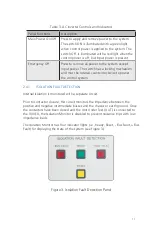
Page 52: ...Fault Display Table 7 Fault Indications Isolation Fault Indicator Bus Fault On Steady Loss of isolation between the positive or negative bus Isolation Fault Detection Reset Flashing Isolation fault has been latched ...

Page 53: ...Appendix A Glossary of Terms ...

Page 54: ...nt which will increase as the filter gets clogged Battery Cycler A term for the 900 EX that refers to its use in battery charge and discharge cycling Configuration The wiring arrangement used for a particular load or loads Also the selection on the DC Converter front panel that matches the physical load connections Command Mode See Control Mode below Control Mode The DC Converter s control algorit...

Page 55: ...EEE Standard 142 199 Recommended Practice for Grounding of Industrial and Commercial Power Systems Section 250 Grounding of NEC and all local codes and ordinances Webasto recommends no more than 0 1 Ohms between all equipment and ground Use copper conductors and terminal lugs only Independent One of three load configurations see also Parallel and Multi Unit Parallel Two loads may be controlled ind...

Page 56: ...ing Limits The maximum and minimum operating points for the DC output Upper limits and lower limits may be set on Voltage Current and Power Operating Space The area enclosed by operating limits on the DC Converter as plotted on a graph of voltage versus current Parallel One of three load configurations see also Independent and Multi Unit Parallel One load is attached to the paralleled positive and...

Page 57: ... information from the 900 EX and sends operating limit and control commands to the 900 EX Side A Also Converter A The master or left converter in the DC Converter Side B Also Converter B The slave or right converter in the DC Converter Standby Mode An operational mode in which the output terminals are internally disconnected and no power transfer occurs Utility AC three phase power source ...

Page 58: ...52 ...

Page 59: ...Appendix B DC I O Connector Assembly ...

Page 60: ...ng the ends of the retaining wire with the supplied copper foil 4 Insert the cable end into the conductor pin Verify that the foil completely covers the cable where the set screws are to be inserted 5 Install the 5 8 18 set screws and torque to 150 in lbs 6 Insert the conductor pin into the insulator sleeve Coating the inside of the insulator sleeve and the pin shaft with ECT silicone spray or cab...

Page 61: ...ble 350MCM 1000Vac rated to connect to the 500A load B 2 2 GENERAL The DC output cable entry hole is provided on the top of the unit in the front right hand corner The cables should be suitably routed through the hole and brought down into the output connection box In order to achieve that the right hand side panels need to be removed Figure 25 shows the cables entering from the top hole Figure 25...

Page 62: ...56 1 Strip cable insulation back 1 inch from the end 2 Tighten the cable into the solid copper lug with a half inch 1 2 stud size 3 Connect the lug with marked cable to the DC terminals ...

Page 63: ...Appendix C 900 EX Remote Voltage Sense Operation ...

Page 64: ...X can be regulated directly at the load eliminating excessive voltage drop across the cables which carry high current between the 900 EX and the load and yet maintain greater voltage accuracy This is accomplished by utilizing the V Sense connectors provided on the front panel user I O strip This feature is enabled by pressing the front panel labeled RVS button to activate Remote Voltage Regulation...

Page 65: ...59 Figure 26 Connection Diagram for RVS in Independent Mode 2 Parallel Mode In Parallel Mode only the RVS connector on channel A is used with the load connected up as in Figure 13 ...

Page 66: ...60 ...

Page 67: ...Appendix D High Voltage Interlock Wiring ...

Page 68: ...put that channel into Standby Mode open the output contactor and isolate the output of the 900 EX from the load Figure 27 High Voltage Interlock Connector Wiring In Parallel Configuration a break in a specific channel s HV Interlock will open that channel s DC Contactor The firmware will recognize this event and open the other DC Contactor and put the system into Standby Mode thus isolating the ou...

Page 69: ...Appendix E Index ...

Page 70: ...ut 34 DC I O Connector Assembly iii 47 51 DC Output 9 33 34 E Emergency Off 3 4 10 11 33 39 40 42 External Parallel 13 28 F Fault Indications 43 44 Fault Lights 12 43 H HV Interlock 4 15 24 60 I Independent Configuration 13 17 26 27 28 34 35 47 48 56 57 60 Installation ii 2 19 20 21 Intermediate DC Bus 9 13 46 48 Isolation Fault Detection 9 11 12 17 33 44 L Limits 22 26 27 30 31 34 35 37 38 39 48 ...

Page 71: ...ower Applications 6 Precautions 3 R Remote Emergency Stop 9 Remote Operation 31 35 38 39 Remote Operation Interface 14 40 48 49 Remote Operation System 9 13 14 15 16 35 39 40 48 49 Remote Voltage Sense iii 9 15 56 57 S Selecting Mode 35 Side A 49 Side B 49 Standby 12 15 24 35 38 39 40 46 49 60 U Utility 9 20 22 49 V Voltage Verification 43 ...

Page 72: ...22855 03 04 ...

Reviews: