background image

7

7)  Reposition gear box cover D and secure in  

position by retighten screws S.

5)  Feed mains supply cable E through cable 

gland G (Fig. I).

6)  Connect mains supply cable E leads to 

respective terminals in terminal connector K
a) ON/OFF (L = Phase, N = Neutral,  

 = Earthing) 

b) 0-10 V (L = Phase, N = Neutral,  

 = Earthing, D–/D+ = 0-10 V control line). 

Tighten cable gland G.

Fig. I

8) Loosen screws H and I slightly. Aim luminaire 

in desired direction, retighten screws H and I.

Summary of Contents for FLB141

Page 1: ...and secondary Type 2 surge arrestors in compliance with EN61643 11 IEC61643 1 Warning Ensure that all required surge protection measures are in place and acti vated prior to luminaire installation Al...

Page 2: ...clamp FLB141 6 RAIL66 version FLB141 7 Space frame version IP66 IK08 Class I ta 40 C Weight lb for FLB141 6 LED 8 6 for FLB141 7 LED 10 1 Windage area ft for FLB141 6 LED 0 431 for FLB141 7 LED 0 484...

Page 3: ...ecial maintenance work is required Do not use high pressure cleaners In case of component failure due to abnormal circumstances or at end of life replacement must be carried RXW E D VXLWDEO TXDOL HG D...

Page 4: ...DOOLQJ DQG FRQQHFWLQJ WKH OXPLQDLUH Notice I WKH OXPLQDLUH LV PRGL HG E DQ ERG RWKHU WKDQ WKH RULJLQDO PDQXIDFWXUHU WKHQ WKH ZDUUDQW ZLOO no longer be valid and shall become the full responsibility of...

Page 5: ...ith relevant installation instructions 3 Determine desired position of luminaire A on rail X dependent on aiming requirements and proximity to a suitable mains outlet Y 4 Attach clamp B to rail X Tigh...

Page 6: ...in line connector G and tighten Attention On any mains outlet Y that is not used protective cover Z PXVW UHPDLQ UPO VHFXUHG KHFN DQG HQVXUH SURSHU W DQG tightness 6 Loosen screws H and I slightly Aim...

Page 7: ...by loosening screws S 3 Determine desired position of luminaire A on space frame X dependent on aiming requirements Attach clamp B to space frame X Tighten wingnut C 2 Check that rating shown on lumin...

Page 8: ...e gland G Fig I 6 Connect mains supply cable E leads to respective terminals in terminal connector K a ON OFF L Phase N Neutral Earthing b 0 10 V L Phase N Neutral Earthing D D 0 10 V control line Tig...

Page 9: ...www we ef com WE EF LIGHTING United States of America Tel 1 724 742 0030 Fax 1 724 742 0035 info usa we ef com TO9248W0422 WE EF 2022 Technical specifications are subject to change...

Page 10: ...WE EF LIGHTING Installation and Maintenance Instructions RAIL66 Projector and Floodlight Mounting System...

Page 11: ...ction with and engineered for a dedicated range of OXPLQDLUHV 3 ODVV WD 6XLWDEOH IRU ERWK LQWHULRU DQG H WHULRU DSSOLFDWLRQV 5 81 9 56 L1 L2 310 9200 0DLQV RXWOHWV 310 9202 0DLQV RXWOHWV 310 9210 0DLQ...

Page 12: ...VW DSSOLFDEOH UHJXODWLRQV DQG UHOHYDQW OHJLVODWLRQ ODLPV EDVHG RQ GHIHFWV DWWULEXWDEOH WR LPSURSHU LQVWDOODWLRQ DSSOLFDWLRQ RSHUDWLRQ DQG RU DQ PRGL FDWLRQ FDUULHG RXW E WKH SXUFKDVHU RU WKLUG SDUWLHV...

Page 13: ...RXJK FDEOH JODQG G 7LJKWHQ FDEOH JODQG G 7 Connect mains supply leads to respective terminals in terminal connector H L Phase N Neutral Earthing Installation RAIL66 UNIVERSAL QVXUH WKDW DOO VXUIDFHV D...

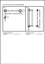
Page 14: ...Flat Surface Fitters pair L 310 9290 Column Fitters pair L 310 9294 Optional Mounting Accessories for RAIL66 UNIVERSAL Fig I Fig II...

Page 15: ...OO WLJKWHQHG DIWHU DOLJQPHQW KDV EHHQ FRQ UPHG 7 Connect mains supply leads to respective terminals in terminal connector J L Phase N Neutral Earthing 6OLGH UDLO DVVHPEO X FDUHIXOO RYHU ZDOO DQJHV C P...

Page 16: ...www we ef com WE EF LIGHTING 8QLWHG 6WDWHV RI PHULFD 7HO D info usa we ef com 72 Technical specifications are VXEMHFW WR FKDQJH...

Reviews: