background image

22

OPERATION OF BURNER (STANDING PILOT)

Starting the Burner:

1.

Depress the gas valve control knob on the combination gas valve and turn to “OFF” (See Figure 15).

2.

Set room thermostat above room temperature and let burner run five minutes to purge the appliance.

3.

Set thermostat below room temperature.

4.

Turn gas valve control to “PILOT”.

5.

Depress red button on valve to start pilot gas flow.

6.

Push red button down on spark igniter until it snaps. Repeat this until the pilot lights. Note: this may take some time until all the
air is “bled” out of the line. The pilot can be seen by looking through the sight glass.

7.

Hold the red button on the valve for 60 seconds, then release.

8.

Observe pilot – if not lit, SHUT OFF BURNER COMPLETELY AND WAIT 5 MINUTES. Repeat steps 1 through 7.

9.

Turn gas control valves to “ON”.

10.

Set room thermostat higher than room temperature so that the burner will start.

To put burner out of operation
1.

Depress the gas valve control knob on the combination gas valve and turn to “OFF”.

2.

Turn off electrical supply.
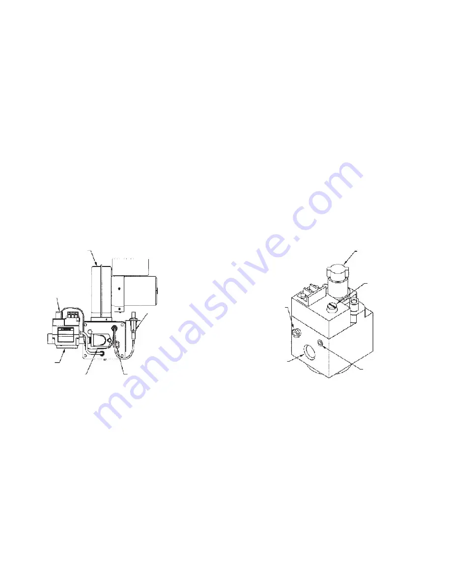
FIGURE 15

Combination Gas Valve

Standing Pilot

Burner

Motor/Blower

Assembly

Control Knob

Thermocouple

Gas Valve

Sight Glass

Spark Ignitor

Control Knob

Regulator

Adjusting Cover

Screw

Pressure Tap

Gas Outlet

Pilot Gas Outlet

Summary of Contents for P250 series

Page 1: ...MENT CSA CERTIFICATE NUMBER 1156769 MODELS WAYNE COMBUSTION SYSTEMS 801 GLASGOW AVE FORT WAYNE IN 46803 PHONE 260 425 9200 855 WAYNECS 800 443 4625 FAX 260 424 0904 www waynecombustion com ALL P250 AN...

Page 2: ...NSTALLER S NAME CONTRACTOR NAME CONTRACTOR ADDRESS CONTRACTOR PHONE NUMBER CONTRACTOR LICENSE DATE OF INSTALLATION COMMENTS ABOUT INSTALLATION START UP THESE INSTRUCTIONS SHOULD BE AFFIXED TO THE BURN...

Page 3: ...E RULES TO AVOID ELECTRIC SHOCK Use only a properly grounded circuit A ground fault interrupter is recommended Do not spray water directly on burner Turn off power before servicing Read the owner s ma...

Page 4: ...ALLATION OF THERMOSTAT SECTION II INITIAL START UP A OPERATION OF BURNER DIRECT IGNITION B OPERATION OF BURNER ELECTRONIC PILOT C OPERATION OF BURNER STANDING PILOT D COMBUSTION ADJUSTMENT OF BURNER E...

Page 5: ...SHOOTING AND DIAGNOSIS 31 G MORE SERVICE HINTS 32 H P250AF P265F IGNITOR POSITION 33 I P250AF P265F WIRING DIAGRAMS 34 SECTION VI PARTS LIST AND EXPLODED VIEWS 39 A P265F EXPLODED VIEWS 39 B P265F PAR...

Page 6: ...er rooms provisions shall be made for supplying air for combustion through special openings one near the floor line and the other near the ceiling each to be sized on the basis of one square inch or m...

Page 7: ...tch or low water cut off inspection shall determine whether either device can be utilized in the gas burner control circuit reference should be made to the American Society of Heating Refrigerating an...

Page 8: ...e of the draft hood where permitted by local building codes If an oil barometric damper has been previously installed this may be used if it is in good condition and any and all weights and or stops a...

Page 9: ...square inch 645 2 mm 2 of the flue area Input Btu hr Kw Draft Hood and Flue Pipe Size Up to 120 000 35 120 000 35 17 180 000 53 180 000 52 75 250 000 73 5 inch 127 mm 6 inch 152 mm 7 inch 178 mm NOTE...

Page 10: ...checked to make sure they are in good working condition When converting oil designed boilers and furnaces it is recommended that the existing combustion chamber be used with the gas burner provided it...

Page 11: ...645 10 25 4 x 10 25 4 210 000 62 122 787 11 27 9 x 11 27 9 240 000 70 144 929 12 30 5 x12 30 5 250 000 76 156 1008 12 31 8 x 12 31 8 Table 2 Combustion Chamber for P265 Only Input Btu hr kW Floor Area...

Page 12: ...ily accessible for inspection cleaning adjustment and repairs INSTALLATION OF MOUNTING FLANGE Position the mounting flange on the furnace wall adjusting orientation as necessary until the bolt pattern...

Page 13: ...ble 4 as assistance in determining closest fractional drill bit size to the number letter drill bit size The correct manifold pressure for natural gas is 3 5 w c 872 Pa Only minor adjustments in the i...

Page 14: ...is 4 5 w c 1121Pa for natural gas and 11 0 w c 2740Pa for L P gas The maximum gas supply pressure is 10 5 w c 2615Pa for natural gas and 13 w c 3238Pa for L P gas Valve is rated for 0 5 PSI or 14 w c...

Page 15: ...The back side is tapered and will make lining up the drill bit easier Deburr the orifice and mark new size on orifice with permanent marker Reinstall the orifice and secure the gas pipe train to the b...

Page 16: ...ad Inch mm 3 8 9 525 3 8 9 525 9 16 14 29 1 2 12 7 1 2 12 7 3 4 19 05 3 4 19 05 1 2 9 16 14 29 13 16 20 64 1 25 4 9 16 14 29 1 25 4 FIGURE 11 PROPER PIPING PRACTICE It is recommended that tables 5 6 a...

Page 17: ...based on 11 w c inlet pressure and a pressure drop of 0 5 w c Special use Piping sizing between single or second stage low pressure regulator and appliance Maximum Capacity of Pipe Size in Btu per Ho...

Page 18: ...s pilots on other appliances ELECTRICAL WIRING OF BURNER The conversion burner is shipped completely wired It is only necessary to supply the 115 volt circuit thermostat and limit circuit All wiring m...

Page 19: ...are not compatible with the burner operation they should be replaced with the proper controls INSTALLATION OF THERMOSTAT The thermostat should be installed on an inside wall and should be located in t...

Page 20: ...utput This voltage produces a spark at the burner igniter sensor rod igniting the gas flowing around the electrode If flame is not detected during the trial for ignition the ignition control will go i...

Page 21: ...gnition the ignition control will go into a lock out condition If this occurs proceed to the section titled SAFETY LOCK OUT TIME SECOND STAGE MAIN BURNER OPERATION When the pilot flame is established...

Page 22: ...s bled out of the line The pilot can be seen by looking through the sight glass 7 Hold the red button on the valve for 60 seconds then release 8 Observe pilot if not lit SHUT OFF BURNER COMPLETELY AND...

Page 23: ...spreader is used to shape the flame to best suit the firing chamber Depending on the firing chamber the flame spreader can be used to produce a long narrow flame or a short bushy flame FIGURE 16 FLAME...

Page 24: ...ould be minimized with a goal of 100 ppm or less In no case should CO be above 400 ppm Stack temperatures for furnaces and boilers are recommended to be between 350 and 400 degrees Fahrenheit Tighten...

Page 25: ...degrees above room temperature the burner should start automatically If it does not start check pilot If no flame is visible relight pilot following lighting instructions Burners with the letters DI...

Page 26: ...The fan motor will develop 3400 rpm quickly causing the centrifugal endswitch to close The endswitch can be identified by the two red wires coming from the end cap of the fan motor 7 After the endswi...

Page 27: ...not light Module senses Module________ Response________________________________________ flame current S8900A F Ignition spark continues pilot valve remains S8610A F open until system is reset________...

Page 28: ...side 6 Ignition Rod Sensing Rod 7 Ignition Lead 8 T T 24 volt terminal TROUBLESHOOTING GUIDE ELECTRONIC PILOT FOR BURNERS UTILIZING HONEYWELL S8600 IGNITION CONTROL Start the system by setting the the...

Page 29: ...oltage is okay replace gas control if not replace module NOTE If ignition control goes into lockout reset system Check continuity of ignition cable and ground wire Check flame rod Check electrical con...

Page 30: ...the following after disconnecting voltage to the system a Check spark gap Gap should be 1 8 3 2mm 1 32 8mm form H V to ground CAUTION NEVER REPLACE THE COMPONENT BOARD WITHOUT FIRST CHECKING TO ENSURE...

Page 31: ...pecified on manufacturer s data plate See Flame Current See 6 2 Flame not established Arcing to ground 3 No spark 4 Arcing other than across gap 1 Sensor probe incorrectly positioned in flame pattern...

Page 32: ...Possible Reasons a Blower motor endswitch not closed which completes the 24 volt circuit to the gas primary b The blower motor is not reaching full rpm due to debris on wheel c Low voltage to the blo...

Page 33: ...FIGURE 21 P250 DIRECT IGNITION IGNITOR POSITION 7 16 11 1 mm 1 16 1 6 mm 1 4 6 4 mm 1 16 1 6 mm 1 8 3 2 mm Gap 31 64 12 3 mm 1 16 1 6 mm 5 16 7 9 mm 1 8 3 2 mm Gap P265 DIRECT IGNITION IGNITOR POSITI...

Page 34: ...bel all wires prior to disconnection when servicing controls Wiring errors can cause improper and dangerous operation Verify proper operation after servicing FIGURE 22 WIRING DIAGRAMS FOR GAS BURNER W...

Page 35: ...35 FIGURE 23 WIRING DIAGRAMS FOR GAS BURNER WITH DIRECT IGNITION FENWAL...

Page 36: ...36 FIGURE 24 WIRING DIAGRAMS FOR GAS BURNER WITH ELECTRONIC PILOT HONEYWELL...

Page 37: ...37 FIGURE 25 WIRING DIAGRAMS FOR GAS BURNER WITH ELECTRONIC PILOT NO T STAT...

Page 38: ...38 FIGURE 26 WIRING DIAGRAMS FOR GAS BURNER WITH ELECTRONIC PILOT FENWAL...

Page 39: ...ide Exploded View of P265F Parts in Exploded View 1 Gas Valve 2 Air Shutter 3 Motor Blower 4 Transformer 5 Model Specification Label 6 Motor Relay 7 Ignition Control 8 Electrode Sensor Ground Rod Asm...

Page 40: ...P265F Parts in Exploded View 1 Gas Valve 2 Air Shutter 3 Motor Blower 4 Transformer 5 Model Specification Label 6 Motor Relay 7 Ignition Control 8 Electrode Sensor Ground Rod Asm 9 T T Terminal 10 Or...

Page 41: ...Base Pedestal Pkg 1 62246 004 Gas Valve EP Models Nat 1 62256 004 Gas Valve EP Models LP 1 62374 004 Gas Valve DI Models Nat 1 62374 PRO Gas Valve DI Models LP 1 62898 001 Orifice Holder Asm 1 60249...

Page 42: ...P250AF Parts in Exploded View 1 Gas Valve 2 Air Shutter 3 Motor Blower 4 Transformer 5 Model Specification Label 6 Motor Relay 7 Ignition Control 8 Electrode Sensor Ground Rod Asm 9 T T Terminal 10 Or...

Page 43: ...250AF Parts in Exploded View 1 Gas Valve 2 Air Shutter 3 Motor Blower 4 Transformer 5 Model Specification Label 6 Motor Relay 7 Ignition Control 8 Electrode Sensor Ground Rod Asm 9 T T Terminal 10 Ori...

Page 44: ...Pedestal Pkg 1 62246 004 Gas Valve EP Models Nat 1 62256 004 Gas Valve EP Models LP 1 62374 004 Gas Valve DI Models Nat 1 62374 PRO Gas Valve DI Models LP 1 62898 001 Orifice Holder Asm 1 Varies Main...

Page 45: ...warrants to those who purchase its Oil Burner Models for resale or for incorporation into a product of resale that its burner is free from defects in material and workmanship under normal use and ser...

Page 46: ...46 NOTES...

Reviews: