


other sections, except top section.
NOTE:
Refer to the Windload Specification Sheet to determine if additional 1/4” - 14 x 7/8”
self drilling screws are required to be installed into the graduated end hinges, as shown.
IMPORTANT:
PUSH & HOLD THE HINGE LEAFS SECURELY AGAINST THE SECTIONS WHILE
SECURING WITH THE 1/4” - 14 X 5/8” SELF TAPPING SCREWS AND OR THE 1/4” - 14 X 7/8”
SELF DRILLING SCREWS. THERE SHOULD BE NO GAP BETWEEN THE HINGE LEAFS AND THE
SECTIONS.
NOTE:
Install lock at this time (sold separately). See optional installation step, Side Lock.
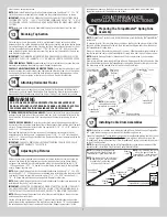
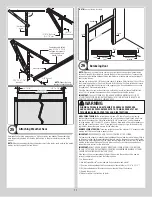
Stacking Top Section
13
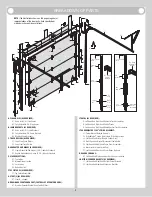
Place the top section in the opening. Install a nail to prevent the top section from falling
backwards. Now, flip up the hinge leaves, hold tight against section, and fasten center hinges
first and end hinges last (refer to step, Stacking Sections). Vertical track alignment is critical.
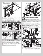
Position flag angle or wall angle between 1-11/16” (43 mm) to 1-3/4” (44 mm) from the
edge of the door; tighten the bottom lag screw. Flag angles must be parallel to the door sec-
tions. Repeat for other side.
IMPORTANT:
THE DIMENSION BETWEEN THE FLAG ANGLES OR WALL ANGLES MUST BE
DOOR WIDTH PLUS 3-3/8” (86MM) TO 3-1/2” (89 MM) FOR SMOOTH, SAFE DOOR OPERA-
TION.
FOR QUICK INSTALL TRACK:
Complete the vertical track installation by securing the jamb
bracket(s) and tightening the other lag screws. Repeat for other side.
FOR FULLY ADJUSTABLE TRACK OR RIVETED TRACK:
Complete the vertical track instal-
lation by securing the jamb bracket(s) and tightening the other lag screws. Push the vertical
track against the track rollers so that the track rollers are touching the deepest part of the
curved side of the track; tighten all the track bolts and nuts. Repeat for other side.
Attaching Horizontal Tracks
14
NOTE:
Depending on your door, you may have Quick Install Flag Angles, Fully Adjustable
Flag Angles or you may have Riveted Vertical Track Assemblies. Refer to Package Contents /
Breakdown of Parts, to determine which Flag Angles / Vertical Track Assemblies you have.
WARNING
DO NOT RAISE DOOR UNTIL HORIZONTAL TRACKS ARE SECURED AT
REAR, AS OUTLINED IN STEP, REAR BACK HANGS, OR DOOR COULD FALL
FROM OVERHEAD POSITION CAUSING SEVERE OR FATAL INJURY.
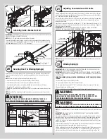
IF YOU HAVE QUICK INSTALL FLAG ANGLES:
To install horizontal track, place the curved
end over the top track roller of the top section. Align key slot of the horizontal track with the
Quick Install tab of the flag angle. Push curved portion of horizontal track down to lock in
place.
FOR OTHER FLAG ANGLES:
To install horizontal track, place the curved end over the top
track roller of the top section. Align the bottom of the horizontal track with the top of the verti-
cal track. Tighten the horizontal track to the flag angle with (2) 1/4” - 20 x 9/16” track bolts
and (2) 1/4” - 20 flange hex nuts.
Next level the horizontal track assembly and bolt the horizontal track angle to the first
encountered slot in the flag angle / angle mount using (1) 3/8” - 16 x 3/4” truss head bolt
and (1) 3/8” - 16 hex nut. Repeat for other side. Remove nail that was temporally holding the
top section in position.
IMPORTANT:
FAILURE TO REMOVE NAIL BEFORE ATTEMPTING TO RAISE DOOR COULD
CAUSE PERMANENT DAMAGE TO TOP SECTION.
Adjusting Top Fixtures
15
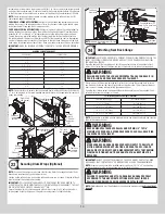
With horizontal tracks installed, you can now adjust the top fixtures. Vertically align the top
section of the door with the lower sections. Once aligned, position the top fixture slide(s),
out against the horizontal track. Maintaining the slide(s) position either tighten the (2) 1/4”
- 20 flange hex nuts / 5/16” - 18 hex nut to secure the top fixture slide(s) to the top fixture
base(s). Repeat for other side.
NOTE:
Refer to the Windload Specification Sheet to determine if additional 1/4” - 20 x 9/16”
track bolt and (1) 1/4” - 20 flange hex nut is required to be installed into the top fixture slide.
Lock each of the top fixture slide in position using (1) 1/4” - 20 x 9/16” track bolt and (1)
1/4” - 20 flange hex nut through any aligning hole. Repeat for other side.
NOTE:
Refer to the Windload Specification Sheet to determine if pushnuts are required to be
installed onto the shaft of track roller stems.
IMPORTANT:
ACCURATELY POSITIONING THE PUSHNUT ONTO THE ROLLER STEM IS CRITI-
CAL. ONCE THE PUSHNUT IS PUSHED ONTO THE ROLLER STEM, THE TABS MAKING CON-
TACT WITH THE STEEL SURFACE WILL MAKE IT DIFFICULT TO REPOSITION THE PUSHNUT.
NOTE:
When positioning the pushnut onto roller stem, ensure the tabs on the pushnut are
pointing away from roller stem.
Starting with the top fixture assembly, slide (1) pushnut over the roller stem and push the
pushnut towards the outside edge of the top fixture assembly leaving 1/4” spacing between
the outside edge of top fixture assembly and the pushnut. Repeat same process for the
graduate end hinges and the bottom corner brackets on the left hand side of door, then
repeat same process for the right hand side of door.
COUNTERBALANCE
INSTALLATION INSTRUCTIONS
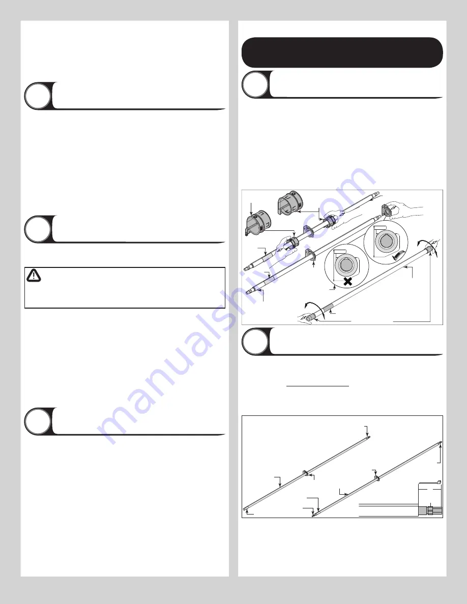
Preparing The TorqueMaster
®
Spring Tube
Assembly
16
NOTE:
TorqueMaster
®
springs come lubricated and pre-assembled inside the TorqueMaster
®
spring tube.
To prepare for install, lay the spring tube assembly on the floor, inside garage, in front of the
door, and with the labeled end to the left. Next, remove the shipping boots from the ends of
the TorqueMaster® spring tube.
Being cam shaped, the center bushing only fits one way. Slide the center bracket bushing as-
sembly towards the center of the TorqueMaster® spring tube, from the right side, as shown.
NOTE:
Refer to Package Contents / Breakdown of Parts, to determine if you have drum
wraps (optional).
Drum wraps (optional) are marked right and left hand. Beginning with the left hand side, slide
the left hand drum wrap onto the TorqueMaster
®
spring tube. Repeat for the right hand side.
The drum wrap will be secured later, in Step, Securing Drum Wraps.
TorqueMaster
®
spring
tube
Remove shipping
boots and discard.
Label
Left hand drum
wrap (Optional)
Right hand
drum wrap
(Optional)
Label
Label
TorqueMaster
®
spring tube
TorqueMaster
®
spring tube
Center
bracket
NOTE:
Orient profile of
spring tube and center
bracket hole for smooth fit.
Installing Cable Drum Assemblies
17
NOTE:
Cable drum assemblies are marked right and left hand. Cable drums and TorqueMas-
ter
®
spring tube assembly are cam shaped to fit together only one way.
Shake the TorqueMaster
®
spring tube assembly gently to extend the winding shafts out about
5” on each side. For
single spring applications
, there will be no left hand spring in the
TorqueMaster
®
spring tube assembly. Lift the TorqueMaster
®
spring tube assembly and rest it
on top of the flag angles.
NOTE:
Temporarily support the center of the TorqueMaster
®
spring tube assembly until the
center bracket is installed in Step Attaching Center Bracket to Wall.
5”
Center
bracket
Winding
shaft
Winding
shaft
Winding
shaft
Winding
shaft
TorqueMaster
®
spring tube
Center
bracket
Label
Label
TorqueMaster
®
spring tube
TorqueMaster
®
spring tube
NOTE:
For single spring applications,
there will be no left hand spring in the
TorqueMaster
®
spring tube assembly.
NOTE:
If winding shaft is not visible out
of the right hand side, gently shake the
TorqueMaster
®
spring tube until
winding shaft sticks out 5”.
NOTE:
If both winding shafts are
not visible, gently shake the
TorqueMaster
®
spring tube until
both winding shaft sticks out 5”.
7


