- 14 -
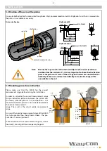
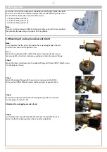
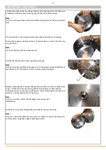
The wire fixation unit has to be screwed into the piston of the cylinder and locked
with counter nut.
Note:
Use screw locking device. If it is not possible to work through the cylinder head
bore, you have to take off the cylinder head (please refer to the cylinder manual).
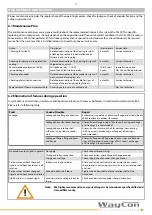
Install 3 stud bolts at the cylinder head.
It is necessary to use stud bolts on the underside of the Sensor flange, as
conventional screws (e.g. according to DIN 912) cannot be mounted for space
reasons.
Note:
Studs have to be greased with MoS2 during assembly, unless otherwise described.
Please follow the operating instructions for the cylinder.
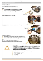
Move the transducer near the cylinder bore. Use a crane if necessary. Remove the
red protective cap at the cable outlet of the sensor. Open the rope clip, guide the
rope through the hole and hang the rope clip in the clip fixation. Finally, close the
rope clip again.
Note:
Do not let the draw wire snap! If the draw wire retracts freely into the
sensor, it can cause injury and damage the device. Take care when unhooking
and retracting the draw wire into the sensor. Avoid leading the draw wire over
edges or corners.
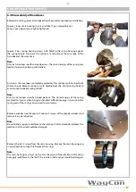
Move the transducer toward the cylinder head and insert the stud bolts through
the bores in the flange.
Note:
Avoid leading the rope over edges or corners. Be careful not to damage the
O-ring. Do not operate the sensor if there are buckles or damages in the draw
wire. Tearing the draw wire may cause injury or damage to the sensor.
Mount the fixing screws through the flange and tighten them crosswise with a
torque of 100 Nm in the first step.
Note:
The fastening screws must be greased with MoS2 during assembly, unless
otherwise described. Please follow the operating instructions for the cylinder.
5 INSTALLATION


