background image

General 


[1] 


1


General 

Topics covered in this chapter: 


Using this manual 


Symbols 


Liability and guarantee 


Incoming goods inspection 


Technical support 


Storage and transport 


Disposal of the device 


China RoHS Compliance 


Installation awareness 


1.1


Using this manual 

This manual contains information concerning the proper and correct use of the device. 

Read the installation guide completely prior to starting installation and operating the 
device. Comply with all safety instructions. 

Include the installation guide when transferring the device to third parties. 


Note 

When requesting technical support, please indicate type and serial number from the type plate and 
the used converter type. 


Table 1


shows a list of documents that are referred to in this installation guide. 


Table 1-1:  Referenced documents 


MHM-97884 

Operating manual EZ 1000, Converter for Eddy 
Current Sensors 

MHM-97879 

Operating manual Machine Studio - General 
Functions 

MHM-97873 

Operating manual A6500-UM Universal 
Measurement Card 

MHM-97442 

Operating manual AMS 6300 SIS, Overspeed 
Protection System 

Summary of Contents for EZ 105 Series

Page 1: ... i Machinery Health Sensor EZ 10xx Eddy Current Sensors Installation Guide MHM 97883 Rev 1 01 February 2019 ...

Page 2: ...RIAL INCLUDING BUT NOT LIMITED TO THE IMPLIED WARRANTIES OF MERCHANTABILITY AND FITNESS FOR A PARTICULAR PURPOSE WayCon shall not be liable for errors omissions or inconsistencies that may be contained herein or for incidental or consequential damages in connection with the furnishing performance or use of this material Information in this document is subject to change without notice and does not ...

Page 3: ... Using the device 7 2 2 Owner s responsibility 7 Chapter 3 Application and Design 9 3 1 The Sensors 9 3 2 The Measuring Chain 11 Chapter 4 Installation and Mounting 13 4 1 Choosing the measuring place 13 4 2 Mount the sensor 14 4 2 1 Requirements and hints for the sensor mounting 15 4 3 Wiring hints 18 4 4 Sensor with extension cable 19 Chapter 5 Technical data 21 5 1 Measuring targets 21 5 2 Meas...

Page 4: ...Contents iv ...

Page 5: ...g the device Comply with all safety instructions Include the installation guide when transferring the device to third parties Note When requesting technical support please indicate type and serial number from the type plate and the used converter type Table 1 shows a list of documents that are referred to in this installation guide Table 1 1 Referenced documents MHM 97884 Operating manual EZ 1000 ...

Page 6: ...ages that occur due to improper use Proper use also includes the knowledge of and compliance with this document Customer changes to the device that have not been approved expressly by WayCon will result in the loss of guarantee Due to continuous research and further development WayCon reserves the right to change technical specifications without notice 1 4 Incoming goods inspection Check the conte...

Page 7: ...ructions Product Support WayCon provides a variety of ways to reach your Product Support team to get the answers you need when you need them Phone 49 89 976713 0 Email sales waycon de Web www waycon biz Note If the equipment has been exposed to a hazardous substance a Material Safety Data Sheet MSDS must be included with the returned materials A MSDS is required by law to be available to people ex...

Page 8: ...ous substances over the Maximum Concentration Value and it has an indefinite Environmental Friendly Use Period Circling arrow symbol with a number This product contains certain hazardous substances over the Maximum Concentration Value and it can be used safely under normal operating conditions for the number of years indicated in the symbol The names and contents of hazardous substances can be fou...

Page 9: ...at meets the requirements of the defined measuring range Ensure an EMC compatible installation including the use of proper cables Ensure proper function of the measurement before activating the measurement for regular operation ...

Page 10: ...General 6 ...

Page 11: ...use the device as specified in this manual If the device is used in a manner not specified by the manufacturer the protection provided by the device may be impaired 2 2 Owner s responsibility If there is a reason to suspect that hazard free operation and thus adequate machine protection is no longer possible take the device out of operation and safeguard it from unintentional operation This is the...

Page 12: ...Safety instructions 8 Related information Environmental conditions ...

Page 13: ...apter The Sensors The Measuring Chain 3 1 The Sensors The 5 mm and 8 mm sensors EZ 105x and EZ 108x are available in different variants With or without the optional EZ 190x extension cable See Chapter 7 for details Figure 3 1 explains the parts of an EZ 105x and EZ 108x Sensor ...

Page 14: ...ead H Threaded part of the sensor case Which sensor type is applicable for a measuring application depends on several requirements such as desired measuring range available measuring track and maximum environmental temperature Each EZ 105x or EZ 108x sensor requires an EZ 1000 converter to complete the measuring chain Use the EZ 190x extension cable to adjust the sensor cable length to the install...

Page 15: ...asuring chain A EZ 1000 converter B EZ 190x extension cable optional C EZ 10xx sensor To achieve a high accuracy the parts of the measuring chain the sensor the sensor cable sensor cable plus optional extension cable and the converter are calibrated together See EZ 1000 operating manual for the calibration details The characteristics of the measuring chain also depend on the material of the measur...

Page 16: ...Application and Design 12 ...

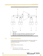
Page 17: ... 1 is an example scheme for where to place the sensors on a turbine shaft to measure the axial displacement shaft vibration or speed Consider the minimum shaft diameter for the sensor type the minimum material width in front of the sensor head and the minimum gap see Section 4 2 1 To measure shaft vibration WayCon recommends using a sensor holder between bearing and turbine housing as close as pos...

Page 18: ... 105x or EZ 108x E Measuring chain for measuring speed key with EZ 1000 and EZ 105x or EZ 108x 4 2 Mount the sensor The following steps describe the mounting of the EZ 105x and EZ 108x sensor types See also the respective EZ 1000 converter manual as listed in Table 1 1 for further details regarding sensor adjustment Prerequisites Calibrated eddy current measuring chain Procedure 1 Screw in the sen...

Page 19: ...ts for the sensor The final adjustment of the sensor depends on the measuring task and requires a complete measuring chain The EZ 1000 converter manual and the manuals for the evaluation electronics such as the AMS 6500 ATG system contain detailed information regarding the final adjustment General holder requirement To mount the sensor use a stiff and vibration free holder with a mounting thread f...

Page 20: ...there is 45 of free space around the sensor head for all sensor types Figure 4 2 Free space around sensor head A At least two threads visible Free space EZ 105x and EZ 108x 45 If you do not ensure the free space specifications the measuring range at the upper end decreases and the linearity error increases Maximum axial tilting angle Ensure that the maximum axial tilting angle a is 2 There is no s...

Page 21: ...imum tangential offset Ensure the maximum tangential offset matches the values in Table 4 1 Figure 4 4 shows the definition of the tangential offset Table 4 1 Maximum tangential offset Sensor type Max offset X Shaft diameter D EZ 105x 0 2 mm 20 mm EZ 108x 0 5 mm 40 mm Figure 4 4 Maximum tangential offset X maximal tangential offset D shaft diameter ...

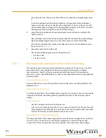
Page 22: ...ls for trigger wheel specifications 4 3 Wiring hints This section contains general information and wiring hints regarding the sensor cable installation As always proper cable installation depends on observations and judgments based on the situation on site Observe the following points for a reliable cable installation Do not bend or twist the sensor cables Cables and connectors must be movable whe...

Page 23: ...le through the bearing pedestal wall machine case below the horizontal joint of the machine and above the residual oil level in the bearing pedestal Do not lead the sensor cable through the upper or removable pedestal cover This could cause problems during machine maintenance and represents a safety concern Place junction boxes on a higher level than the sensor to stop oil from entering the cable ...

Page 24: ...d connection 3 Move the shrink sleeve over the closed connection Plug and socket should be completely covered by the shrink sleeve The black shrink sleeve should evenly overlap plug and socket Figure 4 8 Shrink sleeve in position 4 Use a hot air gun to evenly shrink the sleeve The required shrinking temperature is approximately 200 C 5 Ensure that the shrunken sleeve touches sensor cable plug and ...

Page 25: ...sting of a sensor EZ 105x or EZ 108x and an EZ 1000 converter adjusted to the sensor 5 1 Measuring targets Measuring target shafts and plain surfaces Sensor EZ 105x EZ 108x Shaft diameter 20 mm 40 mm Height of target measuring collar on the shaft 20 mm 25 mm Speed of shaft circumference 0 2500 m s Object material electrical conducting materials Reference material 1 7224 42 Cr Mo 4 AISI SAE 4140 Ta...

Page 26: ...according to API 670 only sensor 4 per 100 K Resistance to chemicals at room temperature Sensor and cable are resistant to water steam natural gas helium bearing oils gasoline benzol nitric acid tetra carbon chloride tetra chloride ethylene Pressure Pressure resistance to sensor head 10000 hPa Sensors are sealed against oil leakage Pressure and differential pressure resistance at cable outlet On r...

Page 27: ...gure 6 1 EZ 1050 xx xx xxx A Unthreaded length see Chapter 7 for available lengths B Case length see Chapter 7 for available lengths C Overall cable length see Chapter 7 for available lengths tolerance 0 10 All dimension in mm ...

Page 28: ...6 2 EZ1051 xx xx xxx A Unthreaded length see Chapter 7 for available lengths B Case length see Chapter 7 for available lengths C Overall cable length see Chapter 7 for available lengths tolerance 0 10 All dimension in mm ...

Page 29: ... not available with 20 mm 0 8 in and unthreaded length case A Case length see Chapter 7 for available lengths B Unthreaded length see Chapter 7 for available lengths C Overall cable length see Chapter 7 for available lengths tolerance 0 10 All dimension in mm ...

Page 30: ... 20 mm 0 8 in and unthreaded length case A Case length see Chapter 7 for available lengths B Unthreaded length see Chapter 7 for available lengths C Overall cable length see Chapter 7 for available lengths tolerance 0 10 D All dimension in mm Cable length D 1 m 30 mm 5 m 300 mm ...

Page 31: ...dering information Sensor Tip diameter Case thread Armored cable Model No 5 mm M8x1 No EZ1050 Yes EZ1051 8 mm M10x1 No EZ1080 Yes EZ1081 Table 7 2 Ordering matrix sensor 1 The 20 mm case is only available with EZ 1050 and EZ 1080 2 The maximum case length of EZ 105x sensors is 100 mm Example EZ1080 02 00 050 EZ 8 mm M10x1 No armor 20 mm sleeve 0 mm unthreaded 5 m cable Model No Case length XX Unth...

Page 32: ...e presented for informational purposes only and while every effort has been made to ensure their accuracy they are not to be construed as warranties or guarantees express or implied regarding the products or services described herein or their use or applicability All sales are governed by our terms and conditions which are available on request We reserve the right to modify or improve the designs ...

Reviews: