[52]
APPENDIX L – SPS5 V9E SYSTEMS’ CONNECTORS AND INDICATORS
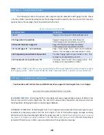
Figure 25: SPS5 V9E Connectors and Indicators
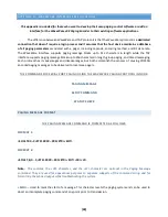
Figure 26: Indicator and Pin-Out Definition Table
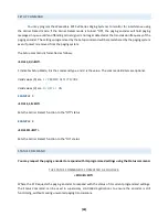
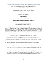
Figure 27: SPS5 v9E-HP Fan Button
(
Note:
If you are using a SPS5
V9E-XL or a V9E-HP, the system
will also have a momentary
button for the fan located on top
of the system’s radio transmitter
for troubleshooting purposes
.)
LED Indicators
RS-232 DB-9 Connector Pin-Outs
Program:
RED LED
– Shows when the system is in or
out of programming mode. It also lights
up if one or more error(s) are found in the
paging system.
(1) CD:
Not used.
(2) RD:
Data Output by the paging system.
(3) TD:
Data Received by the paging system.
Power:
GREEN LED
– Shows Power is on.
(4) DTR:
Not used.
RF TX:
GREEN LED
– Shows transmission of page.
(5) GND:
Grounding Pin.
RF CD:
GREEN LED
– Shows Carrier Detect Status.
(6) DSR:
Signal output by the paging system.
Data:
GREEN LED
– Shows if a RS-232 serial
cable is connected to a host device.
(7) RTS:
Signal input to the paging system.
Needed for Hardware Flow Control.
Ethernet
Port:
GREEN LED
and
ORANGE LED
– Both LEDs
being active indicates normal operation.
(8) CTS:
Signal output by the paging system.
Needed for Hardware Flow Control.
(9) RI:
Not Used

