background image

11 


6.1.3


Serial Mode (over RS485) 

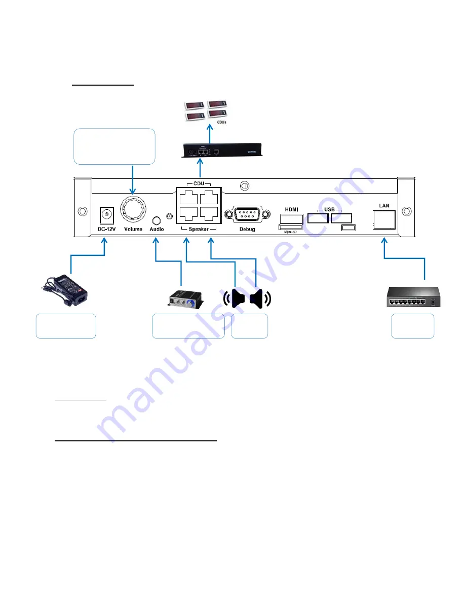
Wiring Diagram:  


Description:  

Connect the Spectra controller as shown in wiring diagram above. 

1) Driving displays (CDUs, SDUs and PDUs): 



In order to drive displays connect one end of patch cord (Straight cable – RJ45 on both 
ends) to port marked “CDU” in Spectra and other end to Active Hub/TCP Active Hub port 
marked “IN”.  


All the End Devices (Displays) can be connected to any of the 16 output ports of Active Hub. 
Refer to Active Hub installation guide for further details, ensure that the DIP switch setting 
of the Active Hub is as per the document and that termination is disabled. 

To connect external 

amplifier or headphone 

(optional)  

Power adapter 

12V 3.43A 

2 x 8Ω 

speaker 

Ethernet 

switch 

Volume Knob - Rotate 

clockwise to increase 

volume 


Summary of Contents for Spectra

Page 1: ...Wavetec Pvt Ltd Haider Ali 9 4 2020 Spectra Controller Installation Guide Rev 1 0...

Page 2: ...2 Document History Revision Date Comments Prepared By 1 0 April 09 2020 First Release Haider Ali...

Page 3: ...t View 6 4 2 Back View 6 5 Ports Description 7 6 Setting up Spectra 9 6 1 Setting up Spectra in wired system 9 6 1 2 TCP IP Mode Recommended 9 6 1 3 Serial Mode over RS485 11 6 2 Providing LAN connect...

Page 4: ...in this document The back side of the controller has all the ports and the front side has the company s logo that glow when unit is powered ON 2 Items Included in Package Item Specs Quantity 1 Spectr...

Page 5: ...5 3 Dimensions and Mounting The Dimensions of the Spectra unit alone are 42 H x 260 W x 170 D mm Dimensions are in mm...

Page 6: ...6 Rack Mount Brackets These two brackets can be screwed on sides of spectra unit in order to mount it on rack 4 Picture of Spectra controller unit 4 1 Front View 4 2 Back View...

Page 7: ...Spectra To connect external amplifier optional Power adapter 12V 3 34A 2 x 8 speaker Volume Knob Rotate clockwise to increase volume Ethernet switch Cat5e Cat6 LAN cable To Active HUB IN Port Only us...

Page 8: ...J45 ports for connecting 8 Ohm speakers Volume Knob for controlling volume level Debug port DB 9 Connector A standard FTDI cable RS232 to USB can be plugged into this port for debugging purpose USB po...

Page 9: ...p Spectra in wired system 6 1 2 TCP IP Mode Recommended Wiring Diagram Power adapter 12V 3 43A Output RS485 Cat5e CAt6 2 x 8 speaker Ethernet switch Volume Knob Rotate clockwise to increase volume To...

Page 10: ...d HTSUs over TCP IP connection to TCP Active Hub TCP Active Hub must be connected to same local network as Spectra is connected to It is recommended to use this mode if using TCP Active Hub for settin...

Page 11: ...ectra and other end to Active Hub TCP Active Hub port marked IN All the End Devices Displays can be connected to any of the 16 output ports of Active Hub Refer to Active Hub installation guide for fur...

Page 12: ...e Patch cord from network switch to LAN port on Spectra controller in order to provide internet or LAN connectivity 6 3 Connecting Speakers There are two RJ45 ports provided on Spectra unit marked AUD...

Page 13: ...13 7 Debugging 8 Upgrading Spectra Updating Patch For upgrading system For upgrading system...

Page 14: ...14 9 External Amplifier Connections 2 x 4 8 speaker Power adapter 12V Audio Aux Cable 3 5mm...

Page 15: ...15 10 Wiring Diagram with whole system...

Page 16: ...16...

Page 17: ...y energy and if not installed and used in accordance with the instructions may cause harmful interference to radio communications However there is no guarantee that interference will not occur in a pa...

Reviews: