


www.teamWavelength.com
© 2005-2019
WTC3293-14001 BOARD WITH DISPLA
Y
PAGE 6
WTC3293-14400-J
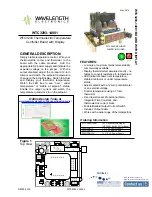
5. WIRE OUTPUT CONNECTOR
Connect the Thermoelectric wires to the Red and Black cable wires as shown. If the polarity is reversed,
the system will only heat. Connect the thermistor wires to the Green and White cable wires (polarity is
not important).
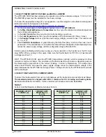
Table 4
OUTPUT CABLE wiring for Thermoelectric
Wire Color
Function
PIN #
RED
GREEN
WHITE
BLACK
1
2
3
4
OUTPUT B - Positive TE wire
SENSOR -
OUTPUT A - Negative TE wire
Table 5
OUTPUT CABLE wiring for Resistive Heater
Wire Color
Function
PIN #
RED
GREEN
WHITE
BLACK
1
2
3
4
OUTPUT B - One side of RH
SENSOR -
OUTPUT A - NO CONNECT
Connect other side of RH to V+
Change RLIM A to 1.5 k
Ω
to limit the
cooling curent to ZERO.
Resistive Heater operation assumes
NTC sensor.
OPERATING THE WTC3293-14001, continued


