


www.teamWavelength.com
© 2005-2019
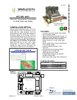
WTC3293-14001 BOARD WITH DISPLA
Y
PAGE 5
WTC3293-14400-J
( )
R
I
=
100,000
(1.89) I
TC
- 1
[Ω]
( )
I
TC
= (0.53)
100,000
R
P
+ 1
[Seconds]
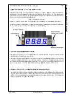
OPERATING THE WTC3293-14001, continued
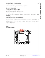
4. ADJUSTING THE CONTROL LOOP
INTEGRATOR TIME CONSTANT
The control loop integrator time constant can
be adjusted by inserting an appropriate resistor,
R
I
, into Control I location to set I
TC
from 0.53 to
4.5 seconds. (Shown in red in Figure 4, prior
page.)
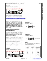
Equation 3 demonstrates how to calculate a
value for R
I
given a desired integrator time
constant. The integrator time constant, I
TC
, is
measured in seconds.
Equation 4 demonstrates how to calculate the
integrator time constant, I
TC
, given a value for R
I
.
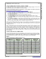
Table 3 lists the suggested resistor values for R
I
versus sensor type and the ability of the thermal
load to change temperature rapidly.
Overshoot with Small Loads
When using the WTC with small, fast loads, the
unit has a tendency to overshoot by up to 10
˚C.
This problem is caused by overcompensation by
the integrator and can be solved by taking the
integrator term out of the system. This can be
done by placing a shorting jumper in the Control
I location.
Table 3
Integrator Time Constant vs Sensor Type and
Thermal Load Speed
Integrator Resistor,
RI
Sensor Type/
Thermal Load Speed
21.4 k
3
Thermistor/Fast
Thermistor/Slow
13.3 k
4.5
1
0.53
4.5
RTD/Fast
RTD/Slow
Open
1
AD590 or LM335/
AD590 or LM335/
Fast
Slow
13.3 k
112 k
112 k
Integrator Time
Constant, [Seconds]
Equation 3
Calculating R
I
from I
TC
Equation 4
Calculating I
TC
from R
I


