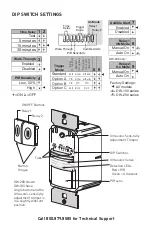
wattstopper DW-103 Installation Instructions Manual Download Page 8

DIP SWITCH SETTINGS

Call 800.879.8585 for Technical Support

8

Auto On

Manual On

Relay 1

ON Mode

7

Disabled

Enabled

Audible Alert

4

High

Low, 50%

PIR Sensitivty

9

1

2

3

4

5

6

7

8

Time

Delay

Walk-Through

ON

Audible Alerts

PIR Sensitivity

5 6

Trigger

Mode

Initial

Occupancy

Maintain Occupancy Re-trigger (seconds duration)

Option C

Both Both

Both

Standard

Both

Either(5)

Either

Option A

Either Either(5)

PIR

Option B

PIR

PIR

PIR

Test

5 minutes

1 2

Time Delay

15 minutes
30 minutes

3

Disabled

Enabled

Walk-Through

Trigger

Mode

DW-203 only:

=ON    =OFF

Relay 1

Relay 2

9

Auto On

Manual On

Relay 2

On Mode

On Mode

1

2

Factory Settings:
 

All models


DW-100 series


DW-200 series

1
2

DELA

Y

PIR 50%

WA

LK

TRIGGER

ALERT

S

RL

Y 1 MAN

RL

Y 2 MAN

ON/OFF Buttons

Button 

Hinges

Tabs

DIP Switches

PIR Lens

Detection LEDs

  Red = PIR

  Green = Ultrasonic

Ultrasonic Cones

Ultrasonic Sensitivity

Adjustment Trimpot

DW-203 shown. 

DW-103 has a 

single button and the 

Ultrasonic sensitivity 

adjustment trimpot is 

in a slightly different 

position.

Relay 2

Relay 1

Summary of Contents for DW-103

Page 1: ...120VAC Time Delay Adjustment 5 to 30 minutes Walk Through Mode 3 minutes if no activity after 30 sec Test Mode 5 sec for 10 min with DIP switch setting PIR Adjustment High or Low DIP switch Ultrasonic Adjustment Minimum to Maximum trimpot Off Frequency 40kHz Light Level Adjustment 8fc to 180 fc Alerts Selectable Audible Visual US Patents 5640113 6617560 7436132 8067906 DW 203 dual relay DW 103 sin...

Page 2: ...d one ON OFF button The DW 203 contains two relays and two ON OFF buttons to allow control of one or two loads independently Pressing a button toggles the state of the corresponding relay DW sensors contain a light level sensor If adequate daylight is present the sensor holds the load OFF until light levels drop even if the area is occupied In the DW 203 light level only affects the load on Relay ...

Page 3: ...alk Through DIP 3 OFF Walk Through mode disabled Trigger Mode The DW sensor has 4 occupancy trigger options set with DIP switches 5 and 6 Determine the appropriate option using the Trigger matrix In the Trigger Mode DIP switch setting table in order to deem the area occupied Both requires motion detection by the PIR and the Ultrasonic Either requires motion detection by only one technology PIR req...

Page 4: ... 1 DIP 9 ON for Relay 2 Auto ON DIP 8 OFF for Relay 1 DIP 9 OFF for Relay 2 With an ON Mode DIP switch in the OFF position the load turns ON and OFF automatically based on occupancy If the load is turned OFF manually Presentation Mode operation applies This prevents the load from turning ON automatically after it was deliberately turned OFF Pressing the button to turn lights ON returns the sensor ...

Page 5: ...wo ultrasonic transceivers operating at 40kHz Detection sensitivity can be adjusted using the trimpot under the ON OFF buttons Service Mode The Service Mode allows the DW to operate as a toggle switch Service Mode turns off all the sensor features and only allows load control through the button s While in Service mode the time delay detection and light level settings are ignored and Ultrasonic tra...

Page 6: ... and tighten 4 Turn the circuit breaker ON Wait one minute then push the Auto ON OFF switch for each load and the lights will turn ON There is a delay due to initial power up of the sensor that only occurs during installation 5 Test and adjust the sensor if necessary 6 Attach the cover plate INSTALLATION WARNING TURN THE POWER OFF AT THE CIRCUIT BREAKER BEFORE INSTALLING THE SENSOR OR WORKING ON T...

Page 7: ...nch circuit Ground Ground Junction Box Junction Box Black Line 1 Red Load 1 Brown Load 2 White Neutral Yellow Traveler White Neutral Black Line 1 Load 1 1 Load 2 2 Black Red Brown Blue White Yellow DW 203 Main DW 203 Remote Black Line 2 Blue Line 2 Ground Junction Box Junction Box Black Line Red Load 1 Brown Load 2 Blue Line White Neutral Yellow Traveler Load 1 Load 2 1 2 White Neutral Black Line ...

Page 8: ...n B PIR PIR PIR Test 5 minutes 1 2 Time Delay 15 minutes 30 minutes 3 Disabled Enabled Walk Through Trigger Mode DW 203 only ON OFF Relay 1 Relay 2 9 Auto On Manual On Relay 2 On Mode On Mode 1 2 Factory Settings All models DW 100 series DW 200 series 1 2 DELAY PIR 50 WALK TRIGGER ALERTS RLY 1 MAN RLY 2 MAN ON OFF Buttons Button Hinges Tabs DIP Switches PIR Lens Detection LEDs Red PIR Green Ultras...

Page 9: ...ut the aid of artificial light In order to set this as the threshold level of brightness so that the artificial lights remain OFF perform the following steps 1 Make sure the room is lit appropriately 2 Put the sensor into TEST mode You have 5 minutes to complete the procedure 3 Press and hold the ON OFF button Relay 1 button on the DW 203 for 3 seconds until you hear a beep 4 Step away from the se...

Page 10: ...ted To verify proper operation set DIP switch 1 to ON then reset switches 1 and 2 to OFF to start Test Mode Move out of view of the sensor The lights should turn OFF in approximately 5 seconds 2 Verify that the sensor is mounted at least six feet 2 meters away from any heating ventilating air conditioning device that may cause false detection Verify that there is no significant heat source e g hig...

Page 11: ...ind industry standard decorator style switch cover plates Cover plates are not included Units come in the following colors which are indicated by the final suffix of the catalog number shown here in parentheses White W Light Almond LA Ivory I Grey G Black B ...

Page 12: ...ee of defects in materials and workmanship for a period of five years There are no obligations or liabilities on the part of WattStopper for consequential damages arising out of or in connection with the use or performance of this product or other indirect damages with respect to loss of property revenue or profit or cost of removal installation or reinstallation 10183r4 9 2013 ...

Reviews: