


36
Wattsonic AIO ESS | USER MANUAL
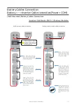
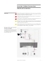
Inverter
B
B
BMS
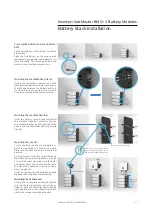
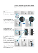
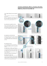
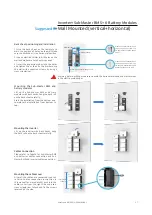
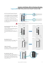
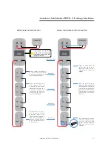
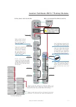
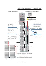
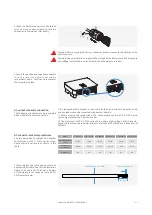
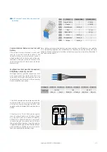
Battery power cables connection
Battery communication cables connection
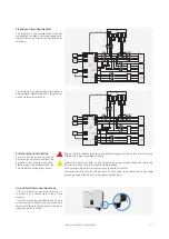
Step1, please plug in Battery
# 1 B - t o S u b - M a s t e r B M S
Battery Input- with the cables in
accessories package.
Step2, then please plug in
Battery #1 B+ to Battery #2
B-,then series connected the
following batter y modules
as indicated by the black line
at right with the cables in
accessories package.
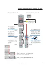
Battery #1
Sub-Master BMS
Battery #5
Battery #6
Battery #2
Battery #4
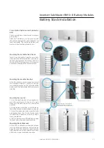
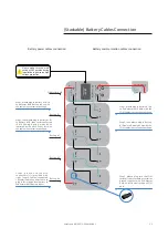
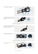
The power cable and com cable can go through the back-sheet
of Battery #4 to hide the cables for better cables management.
The power cable from Battery #6 to Sub-Master BMS(+/+) can
go through the back-sheet of Battery#6, then through the black
cable covers of left string up to Sub-Master BMS to hide it.
Battery #3
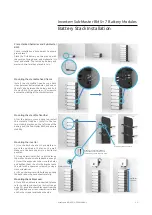
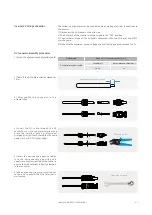
S t e p 3 , p l e a s e u s e t h e M c 4
conn/+) provided with right
length cables(suggested 1800mm)
to make power cable to plug in
Battery #6 B+ to Sub Master BMS
Battery Input+
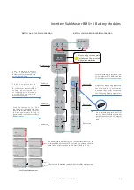
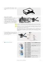
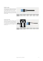
Step3, please plug into the COM
resistor from standard accessories
packed together with Sub-Master
BMS to last batteries open COM
port.
Step2, then please plug in Battery
#1 Down to Battery #2 Up with
the COM cables in accessories
package, then series connected
the following battery modules as
indicated by the dotted blue line.
Step1, please plug in Battery #1 Up
to Sub-Master BMS BMU with the
COM cables in accessories package.
Battery com
Battery Input
Battery Input
Inverter
Inverter COM.
DC ISOLATOR
OFF OFF
Service COM.
Inverter
B+
Down
up
B-
B+
Down
up
B-
B+
Down
up
B-
B+
Down
up
B-
B+
Down
up
B-
B+
Down
up
B-
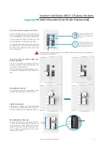
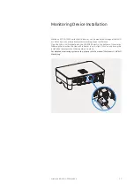
ISub-Master BMS + 6 Battery Modules
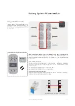
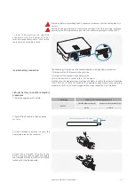
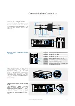
Please make sure the main
switch at OFF position during
installation to guarantee
high voltage protection.
Cross Cables Management
Sub-Master BMS
Battery #1
Battery #2
Battery #5
Battery #6
Battery #3
Battery #4


