background image

Page 12


Connect the Blue Tube from the Faucet to RO Module

Step 26

Step 25

Connect the Red Tube from Faucet to RO Module

a)  Insert the 

fl

 ow control into the end of the red 

tubing coming from the faucet.
b) Insert the end of red tubing into the 

fi

 tting 

labeled “Drain” on the back of the unit.

Insert the blue 3/8” tube from the faucet into the port on the system 
marked “FAUCET”.  Make sure the tube is pushed in all the way 
to the tube stop.

Start up Instructions

NOTE:

If system is connected to an ice maker, turn the ice maker off (or do not allow water to 

fl

 ow to 

the ice maker) until Step 5 “

fl

 ushing” is complete and the tank has been allowed to completely 

fi

 ll. Connection from the RO to the ice maker system should have an in-line valve installed 

before the ice maker so it can easily be closed to prevent water 

fl

 owing to the ice maker 

during start up and periodic maintenance. Your RO tank must be allowed to 

fi

 ll up in order 

for the ice maker system to work properly. (If you are installing an ice maker kit from Watts, 
tee off of the blue line between RO system and faucet).

 After the Tank has 

fi

 lled, open the faucet to 

fl

 ush the tank completely to remove carbon particles 

from 

fi

 nal 

fi

 lter.  Repeat this step two more times.  The fourth tank can be used for drinking. 


*Note:  The 

fl

 ushing of the tank 3 times is only necessary during initial installation. 

This should take about a day to complete.

Open the RO faucet and leave it open until water begins to trickle out, (it will come out 
slowly).

Step 5

Turn on the incoming cold water at the angle stop valve.  Open the needle valve on the brass 
Adapta Valve by turning counter clockwise. Check the system for leaks and tighten any 

fi

 tting 

as necessary.  (Check frequently over the next 24 hours to ensure no leaks are present).

Step 4

Step 3

Step 2

Step 1

This reverse osmosis system contains replaceable components critical to the ef

fi

 ciency  of 

the system. Replacement of the reverse osmosis component should be with one of identical 
speci

fi

 cations, as de

fi

 ned by the manufacturer, to assure the same ef

fi

 ciency and contaminant 

reduction performance. Periodic inspection and following proper system maintenance is critical 
for continued performance. 

After water trickles out of the faucet, close the faucet so the tank will 

fi

 ll with water.  The tank 

will take 6 to 10 hours to 

fi

 ll completely depending on the production capability of the mem-

brane, local water temperature and pressure.

Step 27

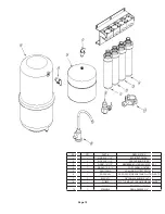
Identify each cartridge and the proper location on the system by 
matching the colors and description.

Install the Cartridges

Step 28

Insert each cartridge with a 1/4 turn in the clock wise direction.  The cartridge 
is installed properly when the label is facing toward the front of the unit.

Note:  The cartridge head swivel up and down for easy access.

Summary of Contents for WQC4 RO SERIES

Page 1: ...proper use with your water supply Save manual for future reference SERIES WQC4 RO Warning Please read carefully before proceeding with installation Your failure to follow the instructions or operating...

Page 2: ...Carbon filter recommended change 6 months The second stage contains a carbon block filter This helps ensure that chlorine and other materials that cause bad taste and odor are greatly reduced Stage 3...

Page 3: ...for the Faucet in a Stainless Steel Sink 5 Faucet Installation 6 Adapta Valve Installation 7 Reverse Osmosis Module Mounting 7 Air Gap Non Air Gap Installation 8 Drain Saddle Installation 9 Tank Valve...

Page 4: ...if copper tubing is down stream of the RO Be sure to follow any state or local regulations Operational Parameters Note The operating pressure in your home should be tested over a 24 hour period to at...

Page 5: ...l or liquid soap to keep the hole saw cool during cutting Step 2 Drill a Hole for the Faucet in a Porcelain Sink Punch a Hole for the Faucet in a Stainless Steel Sink Drill a pilot hole Use a 1 2 Hole...

Page 6: ...llips head screwdriver turn the screw clockwise until the toggle bolt secures the faucet base snug onto the sink top do not over torque toggle bolt 5lb in max Once the faucet base is securely fastened...

Page 7: ...above choosing the configuration that fits your plumbing When attaching the adapta valve to straight pipe threads use Teflon tape on the threads The white tube from inlet side of RO module will be cut...

Page 8: ...Page 8 Non Air Gap Faucet Installation Air Gap Faucet Installation...

Page 9: ...this time The black tubing will be installed later The small square black foam gasket with a circle cut out of the middle must be applied to the inside of the drain saddle Remove sticky tape backing...

Page 10: ...Step 21 Step 20 Adapta Valve Remove a brass nut plastic sleeve and brass insert from the parts bag Place nut on the tube first then the sleeve Small taper end of sleeve must point to the end of tube...

Page 11: ...dle to allow for proper drainage Step 24 Note Note Step 23 How To Use the Quick Connect Fittings on the RO Module To make a connection the tube is simply pushed into the fitting It is essential that t...

Page 12: ...tank 3 times is only necessary during initial installation This should take about a day to complete Open the RO faucet and leave it open until water begins to trickle out it will come out slowly Step...

Page 13: ...the cartridge to the vertical position Step 7 The Sediment cartridge and pre carbon cartridge should be changed every six months Step 2 Cartridge replacement is made easy with the Watts Kwik Change sy...

Page 14: ...he faucet and allow the tank to empty and then close the faucet Replace the post carbon filter cartridge Annual Maintenance Storage Tank Sanitization Step 1 Step 2 Step 3 Step 4 Step 5 Step 6 Step 7 S...

Page 15: ...on Use If the system will not be used for an extended period more than 2 months perform the following Turn on the water supply at the adapta valve Step 1 Step 2 Step 3 Step 4 Step 5 Turn off the incom...

Page 16: ...15 4 Noise from faucet or drain Air gap faucet Inherent sound with air gap faucets Location of drain saddle See diagram for proper location of drain saddle Higher capacity membrane Normal with high c...

Page 17: ...Purchase __________ Date of Install ___________ Installed by __________________ Serial No _____________________ Date 1st stage Sediment 6 months 2nd stage Carbon 6 months 4th stage Carbon 1 year 3rd...

Page 18: ...2 The hardness of the water should not exceed 10 grains per gallon or 170 ppm 3 Maximum incoming iron must be less than 0 2 ppm 4 The pH of the water must not be lower than 2 or higher than 11 5 The i...

Page 19: ...10 11 13 MEMBRANE FILTER 50 OR 100 GPD 4 1 WQGAC 10 11 13 POST CARBON FILTER 5 1 FRO 132 WH 4 GALLON WHITE STEEL TANK 6 1 ROPRO4 W RO ROPRO STORAGE TANK WHITE PLASITC 7 1 BV9014W 3 8 FEMALE ELBOW SHU...

Page 20: ...Page 20...

Reviews: